


LIBRARY
Computational Fluid Dynamic Analysis and Design of an Air Duct Cooling System for 18 kW, 500 kHz Planar Transformers
Year: 2021 | Author: Minh Ngo | Paper: S13.5
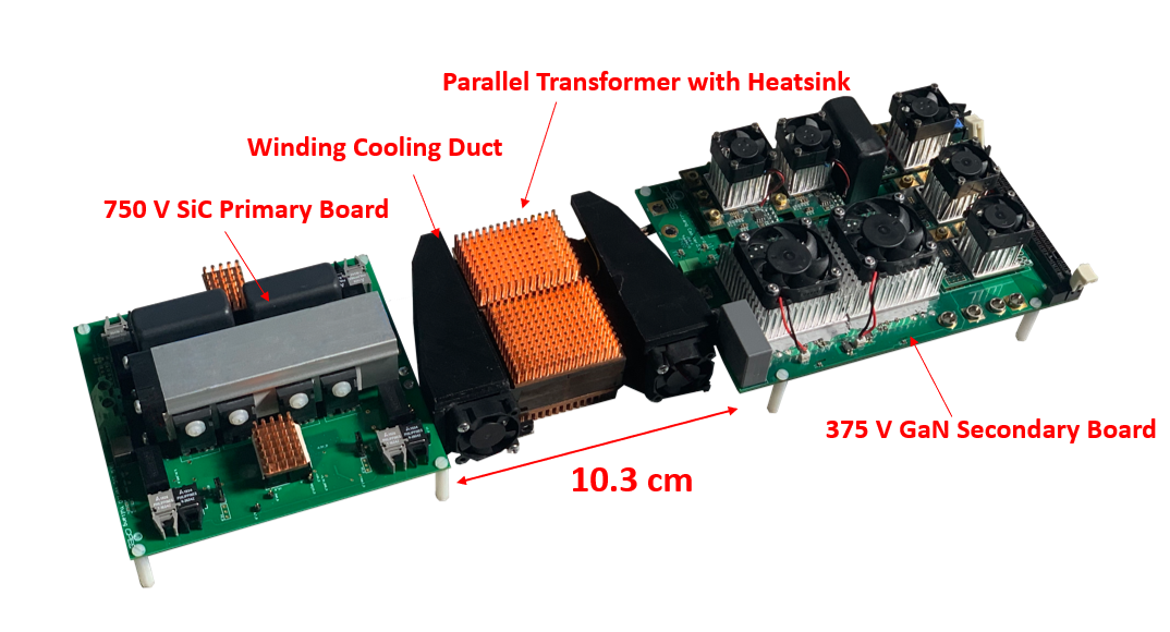
Fig. 1. 18 kW battery charger with cooling ducts.
However, shrinking transformer size increases thermal stress and cooling system size. This work presents an air duct cooling system that was designed using computational fluid dynamics for two parallel (8:4 and 10:1) 18 kW, 500 kHz planar transformers. A 1U low profile forced air cooling duct with converging geometry and integrated turbulators is presented to increase free stream air velocity which lowers winding temperature.
Cooling duct design was constrained by three criteria: 1) cooling system power consumption < 5 W, 2) complies with 1U height requirement, and 3) peak internal winding temperature < 120oC. The 18 kW battery charger with 3D printed cooling duct system is shown in Fig. 1. Turbulators were added to the 30 mm x 30 mm (inlet area) duct to improve air velocity and better deposit airflow onto the winding surfaces as shown in Fig. 2. The addition of turbulators increased average simulated air velocity from 6 m/s to 17 m/s.
The system was constructed and tested to thermal steady state at 10 kW, 15 kW, and 18 kW (full load). At full load power, peak internal winding temperature was only 118oC after steady state was reached. Total cooling system power consumption was only 4 W and the transformer height including the cooling system was only 43 mm. The cooling duct and analytical insights are applicable to future high- power, high-density planar transformers.
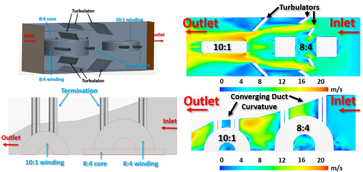
Fig. 2. 30 mm duct with turbulators to improve air velocity and deposit of air flow.
