


LIBRARY
V2 Control with Capacitor Current Ramp Compensation using Lossless Capacitor Current Sensing
Year: 2014
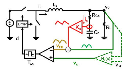
Fig. 1. Concept of V2 control with capacitor current ramp compensation.
Fig. 1 shows the circuit schematic of the proposed control concept with capacitor current ramp compensation. Fig. 2 shows the input voltage transient response of this simulation circuit. As the gain of audio susceptibility is very low, the output voltage is tightly controlled, even without an outer loop.
V2 control is a popular control scheme in point-of-load buck converters and voltage regulators for microprocessors. V2 control using ceramic capacitors is unstable when the converter operates at hundreds of kHz. Moreover, jittering is a common concern in commercial products. Compensating the loop by an inductor current ramp increases the output impedance while compensating the loop by an external ramp, but cannot always achieve desirable damping. This re-search proposes capacitor current ramp compensation for V2 control, which can provide desirable damping to the loop while maintaining an ultra-fast load transient response. Meanwhile, the capacitor current ramp helps to reduce the jittering. The lossless sensing circuit is a simple R-C branch connected in parallel with output capacitors. When the R-C time constant of the sensing branch matches with the time constant of the output capacitor, the capacitor current is emulated by the voltage across the sensing resistor. The sensing scheme is very easy to implement in a control IC. The concept and implementation are applicable to V2 control with different PWM modulation schemes, including constant on-time V2, constant off-time V2, constant frequency V2 peak control and constant frequency V2 valley control.
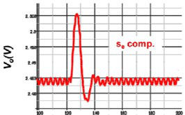
Fig. 2. (a) Output voltage waveforms: se compensation.
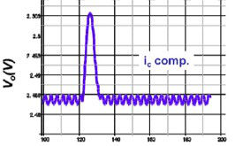
Fig. 2. (b) ic compensation.
