


LIBRARY
A New Inverse Charge Constant On-Time (IQCOT) Control for Noise Performance Improvement in Multi-Phase Operation
Year: 2016
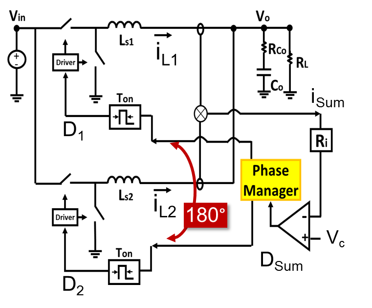
Fig. 1. Conventional COT current mode control structure
This paper proposes a new COT control method based on the inverse charge control con-cept. In Fig 4, a 2-phase constant on time current mode control with proposed structure is shown. In this control, unlike a conventional COT, Vc- Isum is used to charge a capacitor and every cycle cap voltage (Vramp) is compared with a VTH to generate the duty cycle for control. The advantage of the proposed IQCOT control is that, since it is not ripple based controlled when duty cycle approaches the ripple cancellation point and the inductor current ripple becomes very small, there is no noise impact because modulation depends on Vramp signal, which is still very large. Furthermore, at the ripple cancellation point when ripple is zero, the converter can still do its regular operation because Vramp can still be generated by the voltage difference between Vc and IL*Ri. This is shown in Fig. 5, where for 4 phases the converter operates at the ripple cancellation point (at D=0.25 for 4-ph) and the ripple current summation ILsum is zero. However, fsw is decided by the Vramp signal which is 2V in this case. Fig 6 shows the test results of the proposed control where we can see that a 2-phase operation with D=0.5 where Isum is almost negligible.
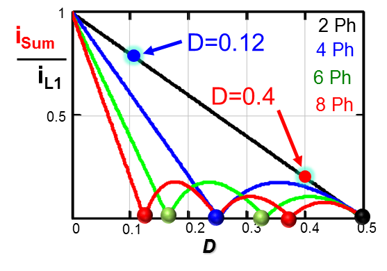
Fig. 2. Ripple Cancellation Effect
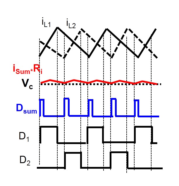
Fig. 3. Small Isum ripple at D≈0.4
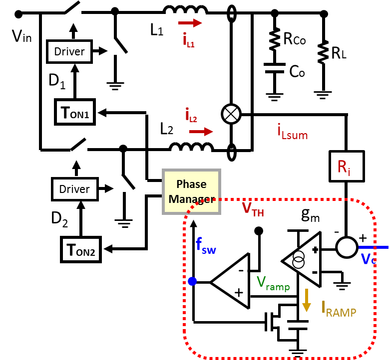
Fig. 4. Proposed IQCOT current mode control structure
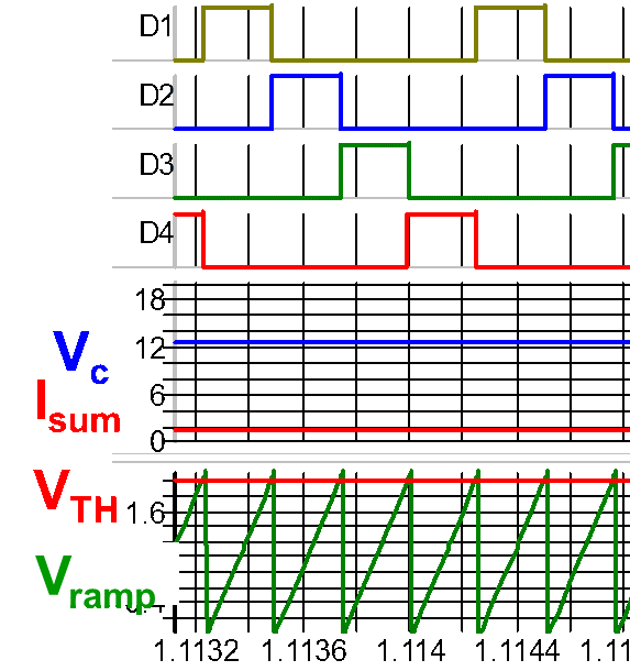
Fig. 5. Proposed structure waveforms at close to ripple cancellation
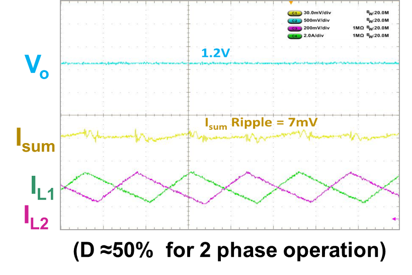
Fig. 6. Test Result waveforms at ripple cancellation point
