


LIBRARY
Modeling and Analysis of High Frequency Interactions for Distributed Power System
Year: 2016
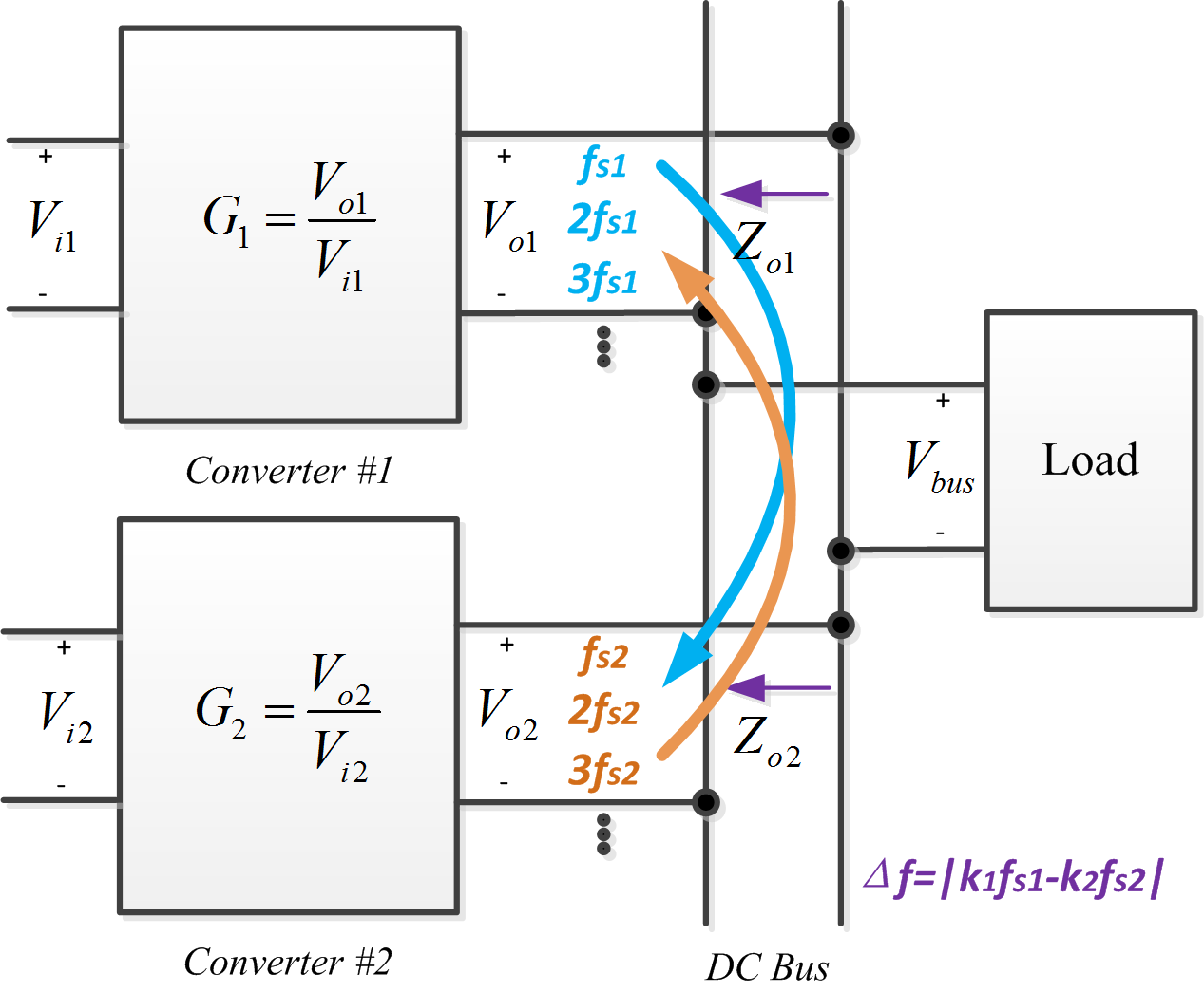
Fig.1 switching frequency ripples' interaction
The voltage mode controlled boost converter is specifically illustrated as a demonstration. For a voltage mode controlled boost converter, the switches and PWM comparator generate multiple sidebands in frequency domain. Therefore, with a sinusoidal current perturbation frequency excitation, the output voltage response contains not only the perturbation frequency but also multiple sidebands and these sidebands can be reordered from low to high and written as f0, f0 - kfs and f0 kfs (0 < fo < fs/2).
This work develops the relationship between output current perturbation and output voltage perturbation at both perturbation frequency and sideband frequencies (we define this relationship as extended output impedance). The frequency characteristics around switching frequency are shown in Fig.2. It can be seen from the figure that the switching frequency is a very important parameter for output impedance characteristics. Although its variation has almost no effect on traditional impedance characteristics, but it affects the relationship between output voltage's sidebands and output current perturbation such as vo(f0) / io(fx).
The high frequency interaction analysis for DPS shown in Fig.1 is based on the proposed model. If the switching frequency of one converter is 20 kHz while that of another is 19.5 kHz, the interaction of switching frequency ripples will produce multiple sidebands. According to the proposed model (as shown in Fig.2), if the low frequency component (f0 = 500 Hz) takes a much larger gain than that of other components, including the perturbation frequency 19.5 kHz itself, then there will be a 500 Hz oscillation in the bus voltage. The simulation result is shown in Fig.3. However, if the two converters' switching frequencies are both 20 kHz, from Fig.2, there will be no oscillations in the bus voltage. The simulation result for this case is shown in Fig.4.
Therefore, when designing power converters used for DPS, it should be suggested that the switching frequencies be checked and optimized by the proposed method to improve the power quality.
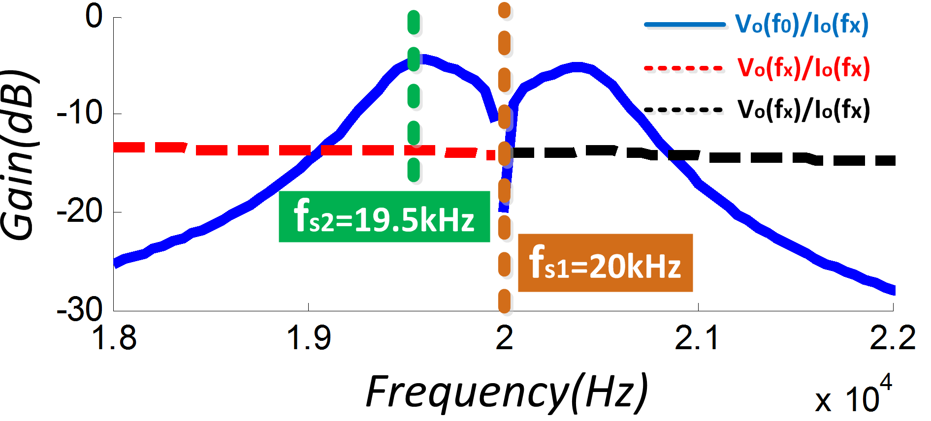
Fig.2 output frequency characteristics around switching frequency
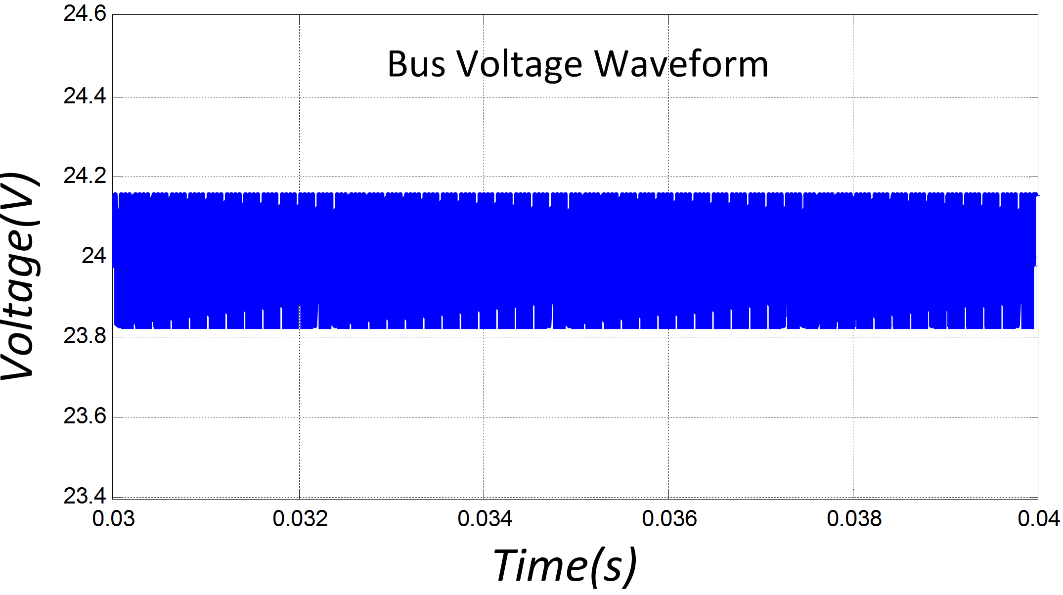
Fig.3 Switching frequencies are both 20 kHz
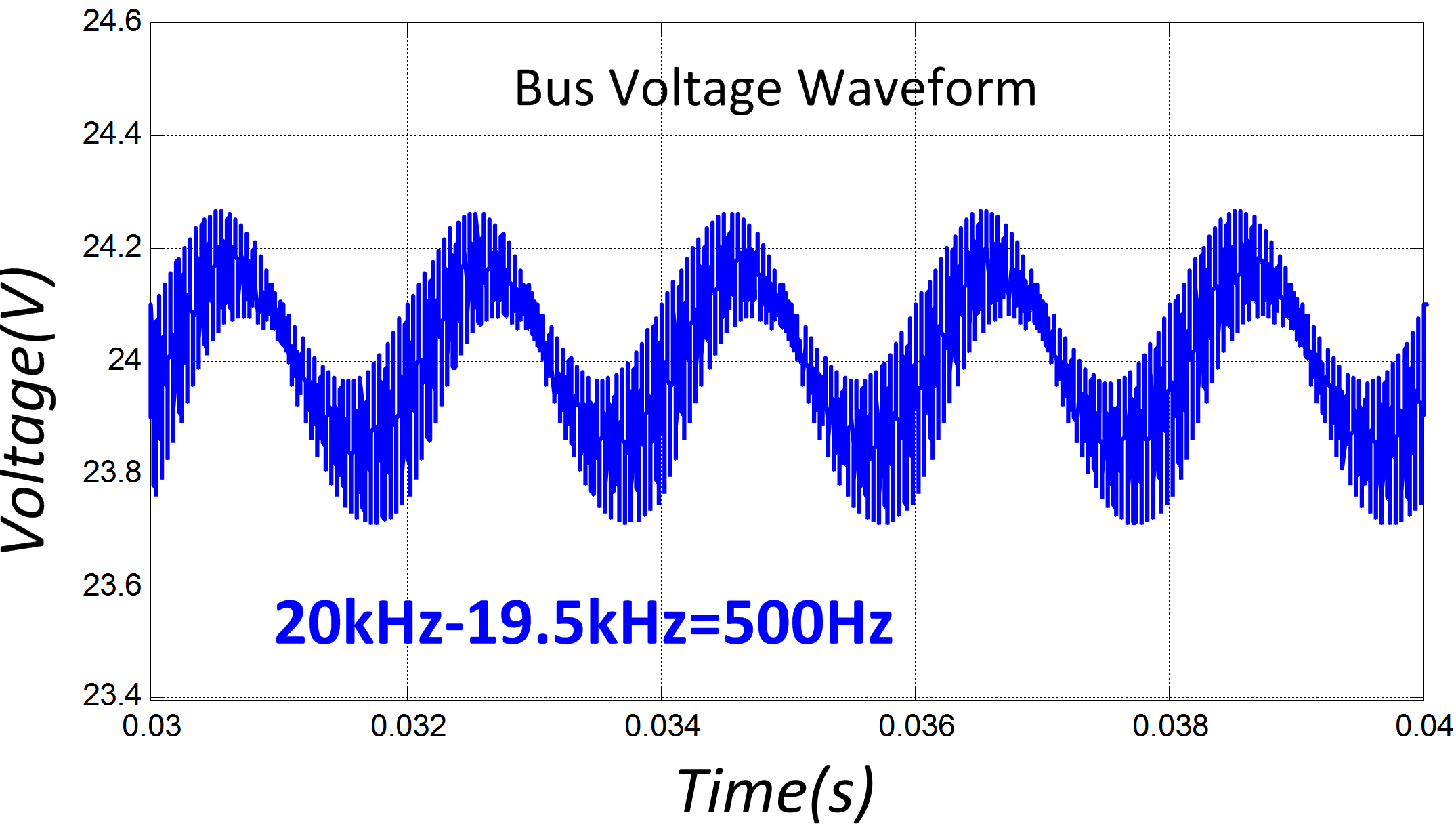
Fig.4 Switching frequencies are 19.5 and 20 kHz
