


LIBRARY
DC Fault Control of Modular Multilevel Converter with Full-Bridge Cells
Year: 2016
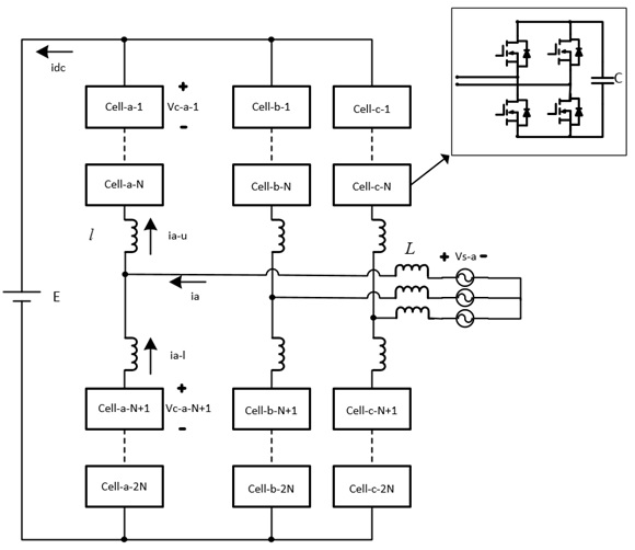
Fig. 1. Configuration of a MMC with FB cells.
Fig. 1 shows the configuration of an MMC with FB cells. Each cell is able to operate with either positive or negative polarity for both voltage and current. In normal operation, the control scheme is divided into three levels. At the circuit level, AC voltage references are generated to regulate active and reactive power. Within each phase, an average voltage control signal and circulating current suppression signal are generated. At each cell, individual voltage control signal and DC voltage references are combined with the aforementioned control signals for modulation. The carriers for the cells of one phase have interleaved phase differences.
When a DC short-circuit fault occurs, the upper arm and lower arm are connected in parallel. Arm currents increase quickly because of the voltage difference between the arms. The DC bus current also increases, and the capacitors are discharged. As the DC side does not consume any active power after the fault, the AC source only provides power to adjust capacitor voltages. To mitigate the fault current and restore capacitor voltages, the power control during normal operation is modified for average voltage control during fault operation. The current minor loop in the average voltage control during normal operation is employed to clear the fault current. Based on the fault current, a common voltage reference is generated for all the cells to discharge the arm inductors and decrease fault current. The DC voltage reference is removed to eliminate the voltage difference between the upper and lower arms.
The simulation is carried out in MATLAB Simulink. The converter has seven cells per arm and works in rectifier mode. The DC fault is added at 0.5 s and cleared after 0.3 s. After the DC fault occurs, the magnitudes of the DC current and arm currents increase rapidly. As soon as the DC fault control is activated, the DC current decreases due to the eliminated voltage difference and the fault current control. The capacitor voltages are deviated by the fault arm currents, but are regulated to the nominal value later. AC link currents decrease to around zero; thus the active and reactive power are also around zero. There is no dependence on additional passive components or circuit breakers.
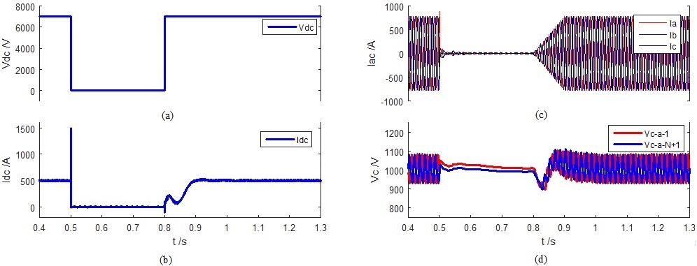
Fig. 2. Simulation Result: (a) DC bus voltage, (b) DC bus current, (c) Three-phase AC source current, (d) Two individual capacitor voltage of Phase A
