


LIBRARY
Startup and Control of High Efficiency 48/1 V Sigma Converter
Year: 2018 | Author: Mohamed Ahmed | Paper: D2.6
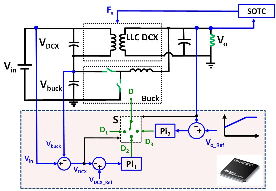
Fig. 1. One-stage 48/1 V sigma converter control architecture.
In this work, a one-stage sigma converter is proposed for 48 V VRM applications. The converter consists of two series-connected converters from the input side, and a parallel converter connected from the output side, as shown in Fig. 1. The power flow is shared between two converters, with the major portion flowing through the higher efficiency path of the LLC-DCX, and the smaller portion flowing through the less efficient buck converter responsible for voltage regulation. This configuration results in a higher total efficiency. The converter was designed with a printed circuit board (PCB) winding matrix transformer for the LLC-DCX, and a PCB winding inductor for the buck converter, thus achieving a very high efficiency of 94 percent and power density of 420 W/in3.
The startup and closed loop control for the sigma converter is challenging due to the presence of the LLC converter which requires special attention to avoid extra voltage and current stresses. But, the combination of the two converters should work together to achieve a smooth and fast startup process.
In this work, a startup method is proposed combining simplified optimal trajectory control (SOTC) for the LLC-DCX, combined with voltage mode control for the buck converter. This method is implemented with a low-cost microcontroller unit, as shown in Fig. 1. The buck converter duty ratio during the startup is generated based on different control laws while implementing the SOTC control for the LLC-DCX.
A prototype was built and tested for conditions of a very fast startup process and minimum stresses for both LLC-DCX and buck can be achieved, as shown in Fig. 2.
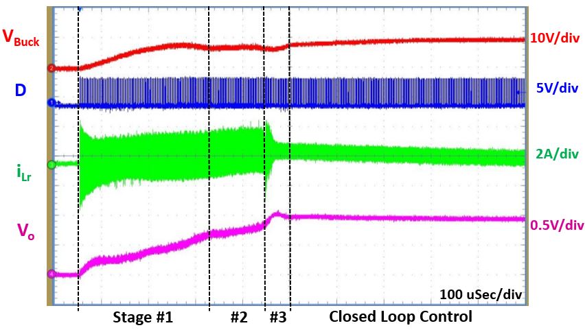
Fig. 2. Sigma converter efficiency startup results at 48 V.
