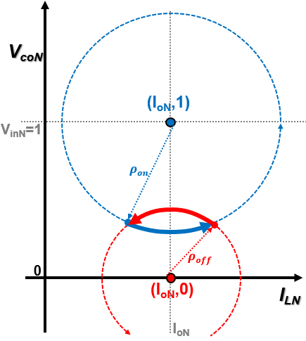
Fig. 1. State-plane trajectory paths of the on-stage (blue) and the off-stage (red) of the buck converter in the normalized state-plane
Voltage regulators (VR) for smartphone CPU applications need to meet fast dynamic voltage scaling (DVS) and load transient requirements. Constant On-Time (COT) control is a popular variable-frequency control due to high-light load efficiency and high-bandwidth design which achieves fast transient. In addition, the V
2 variation of COT is able to achieve fast DVS tracking. Under fast load transient conditions, it is possible for COT to lose control for a period of time. As a result, V
2 COT not only have a large undershoot but also a ringback before control is regained. To analyze the converter behavior when control is lost, the state-plane trajectory of the buck converter is used. The trajectory of the buck converter for a given operating stage, on or off, is represented as a circle in the normalized state-plane, as shown in Fig. 1. Initial condition and circle center information are necessary to determine the state-plane trajectory. When a load step-up transient occurs, the trajectory center moves due to the change in load current. To achieve the fastest transient possible which is a single-cycle response, the converter should be operating in the on-stage during transient and until an optimal switching point is reached. By switching from the on-stage to the off-stage at the optimal switching point, the off-stage trajectory brings the system to the new steady-state in one switching cycle. Using the state-plane trajectory, the optimal switching point (t
E) is determined as the intersection point of two circles, as shown in Fig. 2. In order to calculate the intersection of the two circles, output current (i
o) and circle radii need to be determined. In this paper, a method to estimate the optimal switching point as an inductor current (i
L) function using reference voltage (V
ref) and i
L is presented.
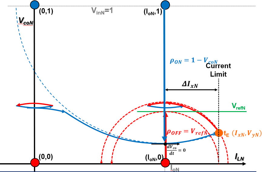
Fig. 2. Proposed state-plane trajectory control to achieve the fastest load step-up transient response


