


LIBRARY
Design of Insulation System in High-Frequency Auxiliary Power Supply for Medium Voltage Applications
Year: 2021 | Author: Ning Yan | Paper: S3.2
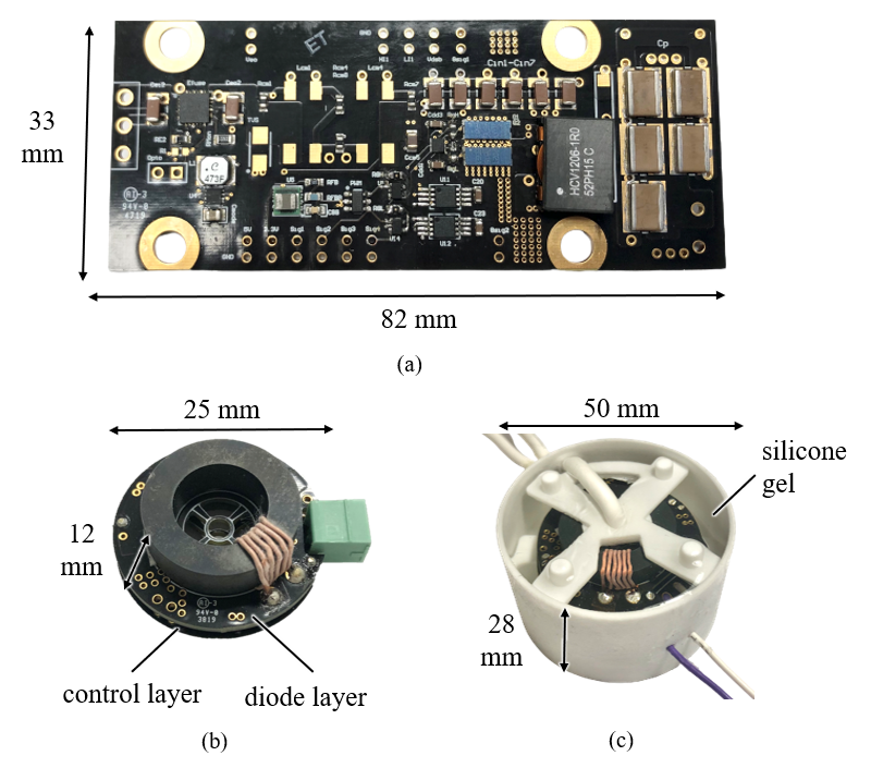
Fig. 1. Hardware prototypes of (a) sending side circuitry (b) air- insulated receiving side circuitry and (c) silicone-insulated receiving side circuitry.
This work first presents the circuit design of a 1 MHz current-fed APS using LCCL-LC resonant topology with a single-turn transformer to reduce the overall size and realize multi-load driving ability. Then, based on the designed APS, eight insulation schemes using different dielectric materials and electric-field (E-field) stress control techniques are introduced. In the analysis, FEM and Q3D simulations are performed to evaluate the E-field distribution and Ccm value for each solution. Considering insulation capability, manufacturability, and Ccm values, as shown in Fig. 1, two designs using air and silicone as insulation materials are selected and evaluated by hardware experiment.
As shown in Fig. 2, with a threshold discharge value of 10 pC, the air-insulated design can achieve PD free of 5.8 kV with measured Ccm value of 1.25 pF. Due to higher dielectric strength, the silicone-insulated design achieves a higher partial discharge inception voltage of 16.4 kV with Ccm value of 3.9 pF. Both designs are able to drive a maximum power of 20 W without any thermal issues. Although in this work, only two solutions are built, all proposed insulation schemes can be applied to other APS system design.

Fig. 2. PD test results for (a) air-insulated design (b) silicone insulated design.
