


RESEARCH
A Testbed for Experimental Validation of a Low voltage DC Nanogrid for Buildings
Year: 2013
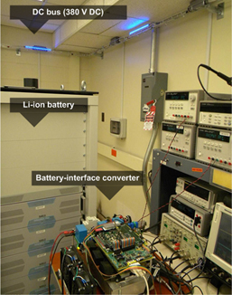
Fig. 1. The laboratory setup showing the 10 kW prototype of the bi-directional battery interface converter, Lithium-ion battery bank and a part of the dc-bus.
The dc nanogrid system presents an integrative solution to satisfy the energy, functional, comfort, and zero-CO2 emission goals for a future building/home environment by utilizing an autonomous operation of the various system components. Although still in the early phase, the testbed described in this paper provides an environment for research, evaluation, and demonstration of advanced technologies for sustainable buildings. It also offers an opportunity to lower down the cost, improve acceptance, and increase the overall energy harvesting efficiency of a renewable energy sources for the future home.
DC nanogrid infrastructure, in some preliminary form, has been built and installed in the lab as depicted in the Fig.1, along with the three components of the nanogrid system: grid-, battery-, and PV-interface converter. Fig. 2 shows one of the experimental waveforms steady state.
The future work on this testbed will, among other tasks, address the major issues of the load sharing and shedding, stability, power management and protection. Additionally, more research effort will be put on the system-level operation including wind generation, PHEV, and constant power loads.
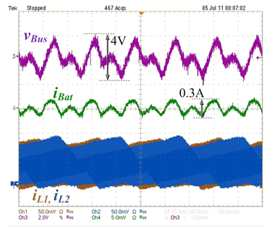
Fig. 2. Bus voltage and battery current ripple in the steady state (iL1 and iL2 are two out of three battery interface converter inductor currents).
