


LIBRARY
Future Home DC-based Renewable Energy nanoGrid System
Year: 2010
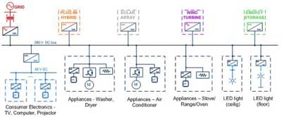
Fig. 1. One-line diagram of DC-based electrical distribution in the future sustainable home.
The future home electrical system is envisioned to have two DC voltage levels: a high-voltage DC and a low-voltage DC local distribution. The high-voltage bus is operating in a range from 360 V DC to 400 V DC with the nominal voltage of 380V DC, powering major home appliances as shown in the Fig.1. Low-voltage distribution is chosen to be 48V to coincide with the standard telecom voltage, powering computer loads, low power consumer electronics and LED lighting.
The big envisioned advantage of the DC system is the fact that the DC architecture can be completely breakerless by having power converters featuring the current limit. There will be only one connection point of the DC bus to the utility grid via the bidirectional voltage source converter.
The concept accepted for the voltage regulation in the nanoGrid system is the adaptive droop control based on the DC-bus signaling technique as shown in the Fig. 2. Having this, communication between the system converters in a sense of control is avoided and converters work in the mode of operation determined by the voltage levels on their terminals.
The nanoGrid has Supervisory Control and Data Acquisition system (nanoSCADA), hybrid DSP and FPGA platform that communicate with all the converters, as well as with all the appliances in the system, through the wireless network channel in order to fully utilize power management algorithms. The nanoSCADA is able to connect to the internet and check the weather forecast for the future period in order to fully utilize energy storage.
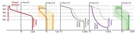
Fig. 2. V-I characteristics of the system converters.
