


LIBRARY
Modeling and Control Design of AC-DC Single-phase Bi-directional PWM Converter
Year: 2008
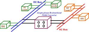
Fig. 1. DC-AC hybrid system configuration.
- Stand-alone inverter mode: when the grid is lost, the converter regulates the ac bus voltage and frequencies feeding the ac loads while the renewable energy sources or energy storage on the dc side to provide power. The ac side renewable energy resources would act as current sources.
- Grid-tied inverter mode: when the grid is connected, the converter acts as a current source injecting or sinking power from the grid to balance the power flow between the dc and ac subsystems, while one of the dc resources regulates the dc bus voltage.
- Grid-tied Rectifier mode: when the grid is present, the converter regulates the dc bus voltage to sustain the dc loads while all dc side energy sources operate as current sources.
- Grid-tied charger mode: when the grid is present, the converter charges the energy storage elements, such as batteries.
By applying the modeling methodology of semi-conductor switches, the switching, average and small signal models of the converter are derived under different modes of operation. Based on the state feedback control theory, one double-loop control scheme is proposed in CPES for all modes of operation. The proposed control scheme was built on a unified inner line inductor current loop that enabled the smooth transition between the different operating modes using multiple switchable outer loops for the specific operating modes. The complete modeling and step-by-step control design procedures can be easily applied and implemented for the single-phase PWM converter. This design procedure can really reduce much effort on control design of single-phase converter application.
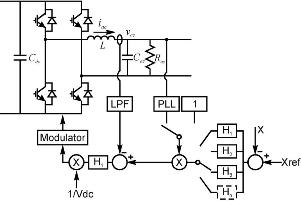
Fig. 2. Single-phase control structure.
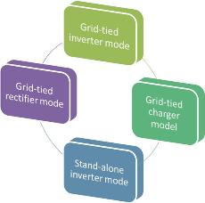
Fig. 3.
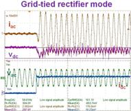
Fig. 4. 7 kW test results.
