Fig. 1
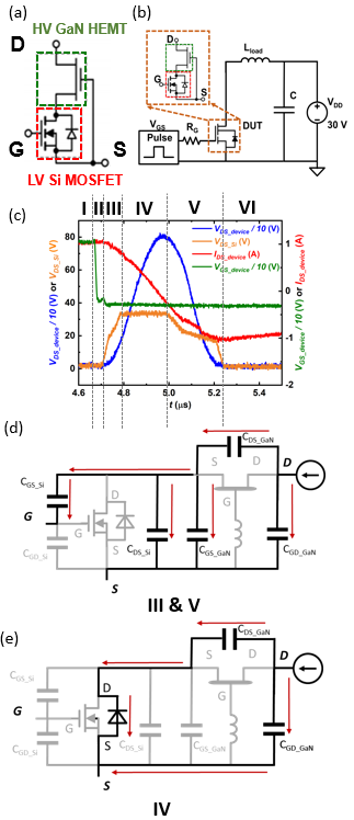
Surge energy robustness of power devices is desired in many applications such as automotive motor inverters and powerlines. GaN high-electron-mobility transistors (HEMTs) have no intrinsic avalanche capability; p-gate GaN HEMTs were recently shown to withstand surge energy with their overvoltage capability. This work, for the first time, studies the surge-energy robustness and failure mechanisms of 650-V-rated cascode GaN HEMTs in the unclamped inductive switching (UIS) tests, which were found to be different from the ones of p-gate GaN HEMTs. The cascode GaN HEMT initially withstands the surge energy through capacitive charging, until V
DC of the cascode device reaches 150 V ~350 V, where the Si MOSFET begins to avalanche. Subsequently, two failure modes are observed, both occurring in the GaN HEMT. The first mode is electric-field (E-field) induced when the peak overvoltage reaches the HEMT breakdown voltage (BV ~2kV) Fig. 2(a)., featured by a short between the HEMT gate and drain (cascode source and drain) Fig. 2(b). In the second mode, the cascode fails at a voltage much lower than the HEMT BV Fig. 2(c), featured by a short between the HEMT source and drain Fig. 2(d). The failed DUT can block voltage and avalanches like a low-voltage Si MOSFET Fig. 2(e). These results provide critical insights on the cascode GaN HEMT ruggedness in surge-energy and overvoltage conditions.
The device under test (DUT) is a commercial 650 V, 50 mΩ rated cascode GaN HEMT Fig. 1(a). Fig. 1(b) shows the schematic of the UIS set-up. The typical DUT safe- withstanding waveform in the UIS test with a 20 µH inductor is shown in Fig. 1(c). Five distinct phases have been identified: (a) Phase I: The DUT is turned ON, the inductor is charged by VDD. (b) Phase II: The Si MOSFET is first turned OFF, then the HEMT is turned off. (c) Phase III: cascode output capacitance (Coss) resonates with the load inductor (L) Fig. 1. (d). (d) Phase IV: Si MOSFET avalanches; the inductor energy is resonantly charging the HEMT CDS and resistively dissipated in Si avalanche simultaneously Fig. 1(e). (e) Phase V: repeat phase III. (f) Phase VI: The DUT is turned on in its 3rd quadrant and the inductor and is gradually discharged by the power supply.
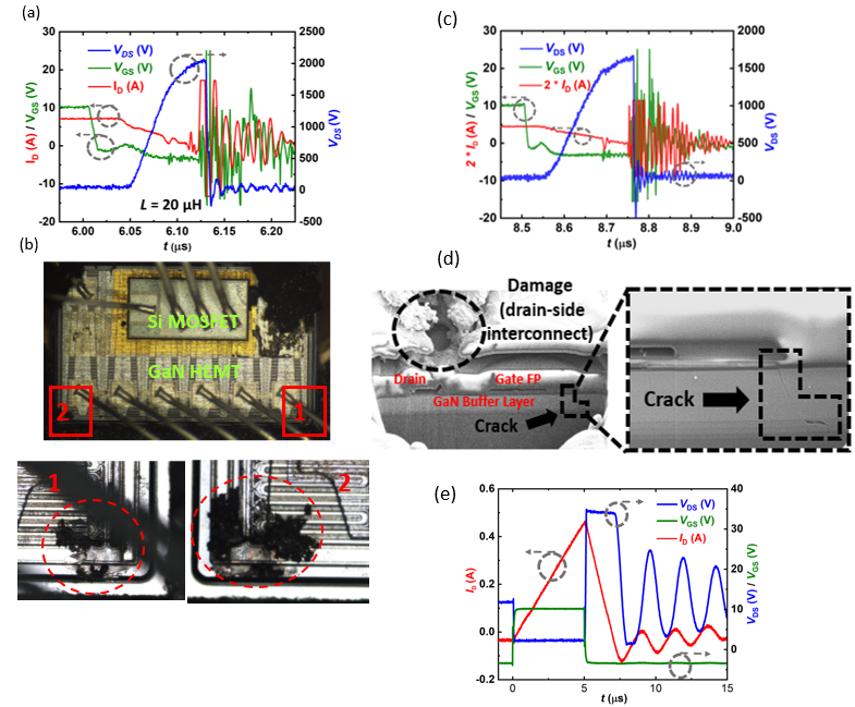
Fig. 2


