


LIBRARY
Partial Fluctuating Power Control of Resonant Converter for Solid-State Transformer
Year: 2022 | Author: Zheqing Li | Paper: H-S4.5
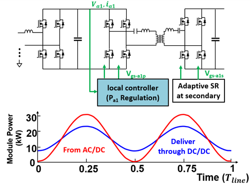
Fig. 1. Control diagram for partial fluctuating power control
In this paper, the benefits and drawbacks of these two methods are compared, under the same design parameters. The bus capacitor is found to be the most critical component in the system from the standpoint of loss and size trade-offs in the two control methods. Factors that impact the loss trade-off for partial fluctuating power control are evaluated.
A method is proposed for calculating the average loss over one cycle that utilizes the proposed fluctuating power flow to predict the loss distribution. A power fluctuation of 50% is selected as an example to illustrate the loss comparison between the partial fluctuating power and the constant power. The total efficiency has a less than 0.1% decrease with the same device. However, a 50% reduction in bus capacitor volume and BOM can be saved. a 15-kW-rated, 200-kHz, 1.6 kV/1.1 kV CLLC converter is developed to verify the concept, which shows 98.9% efficiency for constant fluctuating power flow and 98.8% for partial fluctuating power flow.
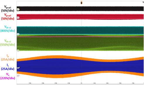
Fig. 2. Experimental waveform for fluctuating power control
in a half-line cycle.
in a half-line cycle.
