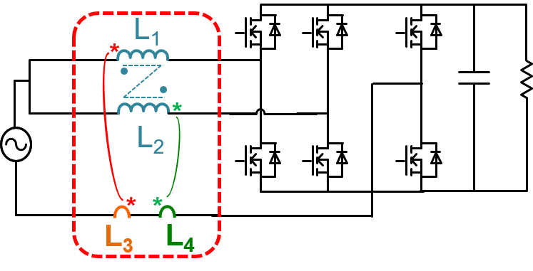
Fig. 1. Two-phase interleaved totem-pole PFC converter
With recent advances in wide band-gap &lbar;WBG&rbar; power semiconductor devices, namely, SiC and GaN, we have witnessed significant improvements in efficiency and power density in power electronic circuits, compared to the current practice using silicon counterparts. Furthermore, with significant higher operating frequency, the integration of magnetic components with embedded windings in the printed circuit board &lbar;PCB&rbar; is feasible. In certain isolated areas, we have witnessed design paradigms by integrating transformers with embedded PCB windings to improve the power density, manufacturability and electromagnetic interference &lbar;EMI&rbar;. The PCB winding-based transformer is able to maintain a similar winding loss compared to the litz wire version by perfect winding interleaving. On the other hand, however, in certain power supplies where PCB winding-based inductors are implemented, dramatic increase in losses has been observed in an extended power range.
In this paper, the fundamental limitation of the PCB winding-based inductor, that is the increased winding losses due to the cumulative effect of the magnetomotive force, is identified. Based on the understanding of the loss mechanism, an approach to reduce the PCB winding loss by breaking down one inductor into several elemental inductors with less number of winding layers is presented. The feasible power range of each elemental inductor unit is studied. Furthermore, a modular approach to extend the power range of PCB-based inductors while maintaining a similar efficiency as litz wire inductor is presented. Moreover, the balance technique is incorporated into the inductor design to suppress the common mode noise emission of non-isolated converters, such as the totem-pole PFC circuit as shown in Fig. 1. A PCB-based inductor example for a 3 kW datacenter server power supply, as shown in Fig. 2, is given to illustrate the benefits of the proposed approach.

Fig. 2. Proposed inductor with embedded PCB winding
,


