


LIBRARY
A Novel Stray-inductance-based Current Sensor for Switching Current Measurement
Year: 2022 | Author: Tam Nguyen | Paper: H-S1.6
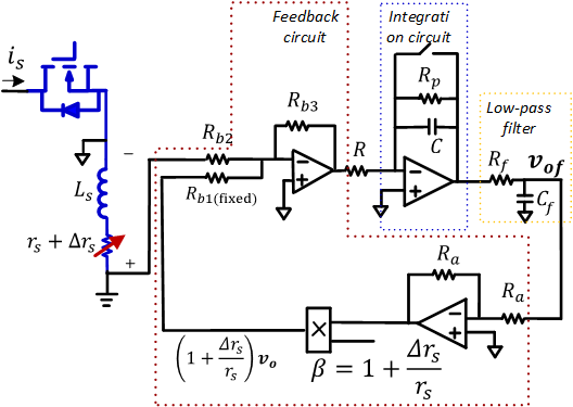
Fig. 1. Proposed current sensor scheme
This work proposes a stray-inductance based current sensor scheme, which provides much improved output compared with existing methods. Firstly, impact of the parasitic resistance on the current sensor is thoroughly investigated. Then, a feedback method with a fixed pole placement is proposed. The current sensors performance is further improved by a dynamic feedback loop, which constantly monitors the change in the parasitic resistance and updates the pole accordingly. As a result, the moving zero caused by the parasitic resistance variation is cancelled regardless of the temperature. The proposed method only requires information of the switching current, which helps simplify the design process.
The proposed current sensor scheme, which includes an integration circuit, a low-pass filter, and a dynamic feedback loop, is presented in Fig. 1. Based on the sensing current waveform, the change in the wire bond resistance between the Kelvin source and power source terminals is calculated. Then, the correction factor, denoted by β, is continuously updated to the feedback loop in Fig. 1 to mitigate the error in the current sensors output caused by the temperature variation. Fig. 2 presents the switching current waveform with the proposed current sensor versus that measured by a commercial Rogowski coil probe, under a DPT test. It is a good agreement between the two characteristics in the on-time interval of the switching device, including the short transient time shown in the magnified area. This indicates that the measurement current with the proposed sensor can be used for both protection and control purposes.
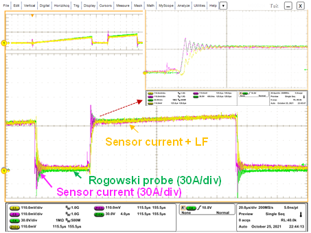
Fig. 2. Sensing current waveform with the proposed sensor and the Rogowski coil at steady state
