


LIBRARY
Magnetic and Thermal Design of Litz wire 500 kHz High Power Planar Transformers with Converging Cooling Duct for a dc Transformer Resonant Converter Applications
Year: 2022 | Author: Minh Ngo | Paper: T-S2.5
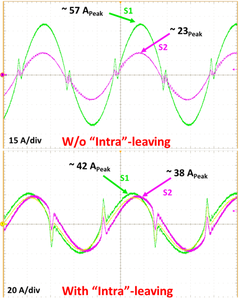
Fig. 1. Current sharing results with and without "Intra-leaving"
Conventional air-cooling design simply adopts an over-sized high airflow fan to keep the transformer within a desired thermal limit, which reduces power density and efficiency. This work seeks to address this trade-off by presenting a high density, low profile, forced air cooling duct system for high frequency transformers. Different cooling duct designs are presented and analyzed considering the trade-offs between design complexity and cooling performance. A pair of 500 kHz planar transformers with 18 kW ratings are used to demonstrate the proposed cooling system and achieves a power density of 635 W/in3, peak height of 43 mm, cooling power consumption of 6.8 W, and 8% peak temperature reduction when compared to cooling the transformers with a 120 mm x 120 mm, 25 W fan. Peak winding temperature at 15 kW load was 106° C and peak core temperature was 72° C. The proposed transformer with cooling ducts also achieves four times higher power density than the set up using a 120 mm x 120 mm fan.
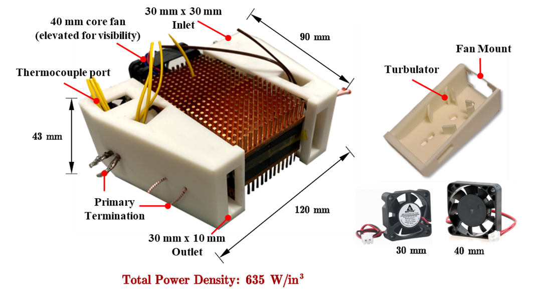
Fig. 2. Proposed Cooling System with Converging Cooling Ducts
