LIBRARY
Fault-Monitoring of Photovoltaics Systems using Impedance Measurement

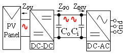
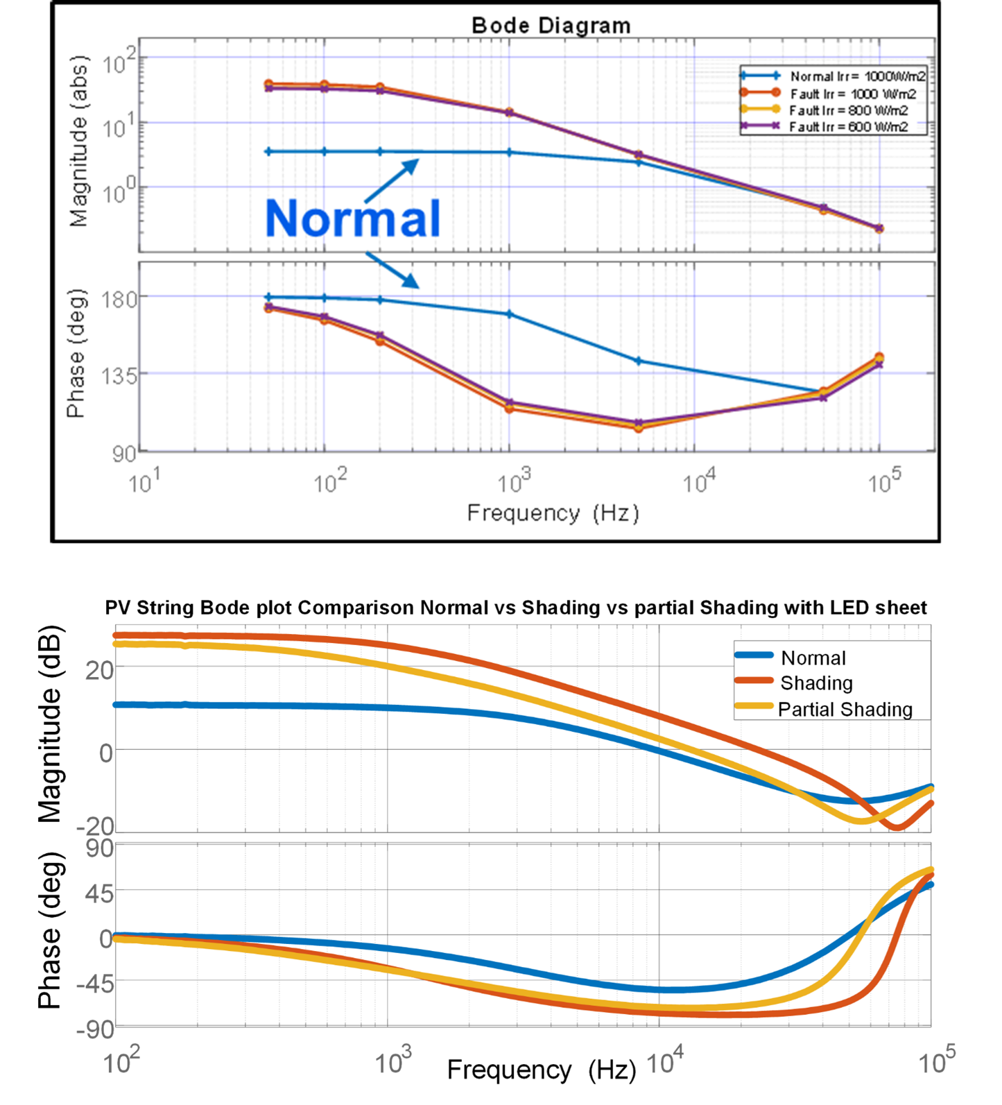
Using power converters and inverters a small signal is injected into the PV panel as shown in Fig. 1 and the impedance of the PV panel is computed. Due to mismatching of electrical characteristics among PV cells, the PV string operates at a suboptimal point. The cause of mismatching can be manufacturing error, PV cell shading, or cell degradation. Partial shading of a PV cell can lead to the cell being operated in reverse bias condition. Thus, PV cells will be sinking power rather than source and leading to an increase in cell temperature. High PV cell temperature will eventually lead to cell degradation and create a hot spot (HS) in a PV mod-ule. A Simulink-based model is simulated with 20 monocrystalline PV cells under standard illumi-nation of 1000 W/m2 and temperature 25 °C. With fault conditions, the illumi-nation on the faulty PV cell is 0 W/m2 and temperature of 75 °C. The results are compared to experimental results. Under the low-frequency region, the magnitude of imped-ance for faulty PV cells is higher than the normal PV cells. For the mid-frequency region, the phase of impedance for the faulty PV cell is higher than the normal PV cell as shown in Fig. 2.
With the impedance measurement tool, changes in impedance are seen for PV cells under fault scenarios. Equipment-based hardware results for impedance measurement of a PV cell well matches with the model and the general trends are consistent.


