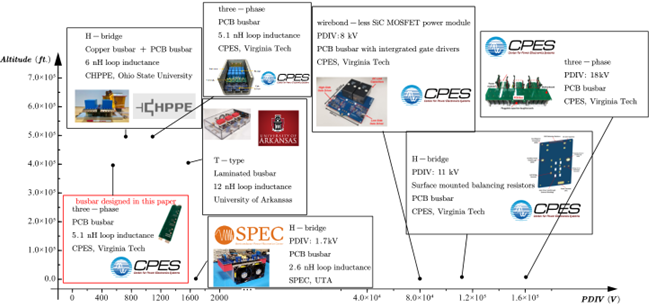
Fig. 1. State-of-the-art busbar designs: altitude vs. insulation voltage.
Among the components of a powertrain converter, the busbar is a key contributor of weight and cost. The conventional laminated busbar is assembled by laminating together stacked copper plates and insulator layers such that the stray inductance cannot be as small as it would be without the added thickness of the insulation layers. The printed circuit board (PCB) busbar has a structure similar to that of the laminated bus; however, with the automated fabrication processes and vacuum lamination, the PCB busbar is able to use a much thinner insulation layer while meeting the same required level of voltage insulation. Meanwhile, the thinner insulator leads to smaller stray inductance. This is especially beneficial for aviation applications due to the dramatically lowered partial discharge inception voltage (PDIV) at high altitudes. Based on the insulation voltage and the operating altitude, the state-of-the-art busbar designs are summarized in Fig. 1.
A modularized 500V-rated three-phase PCB busbar design is introduced to address density and insulation concerns. Several busbars can be connected in series and/or parallel to drive the multiphase machine. The PCB busbar design aims to be partially discharge-free at 40,000 ft. The following will be detailed in the full paper: Peak electric field intensity in the PCB busbar is optimized in the PCB layout to lower the insulation stress; a frequency-dependent busbar modeling approach is introduced to derive the current distribution and extract the busbar loss; the commutation loop inductance and switching transient verifications will be provided.


