LIBRARY
Failure Modes and Effects Analysis (FMEA) of 10 kV SiC MOSFET-based 7-Level 13.8 kVac 22 kVdc Multicell Converter

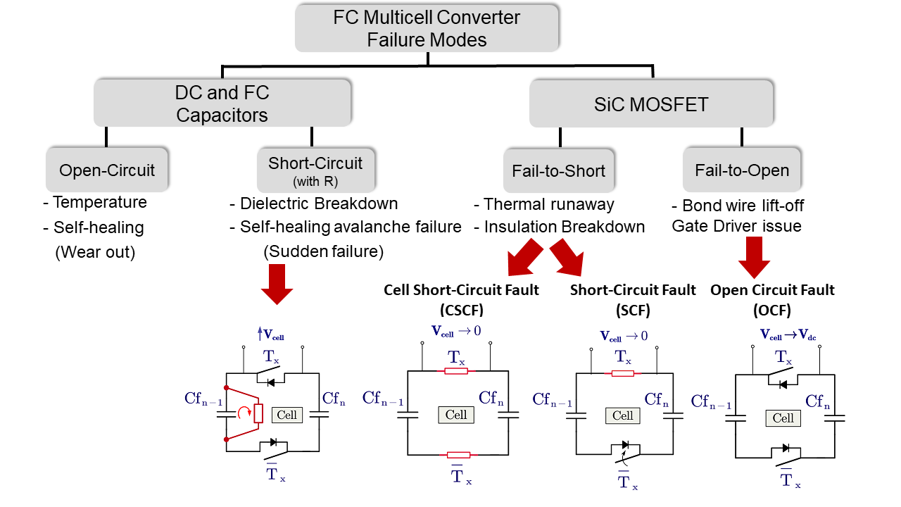
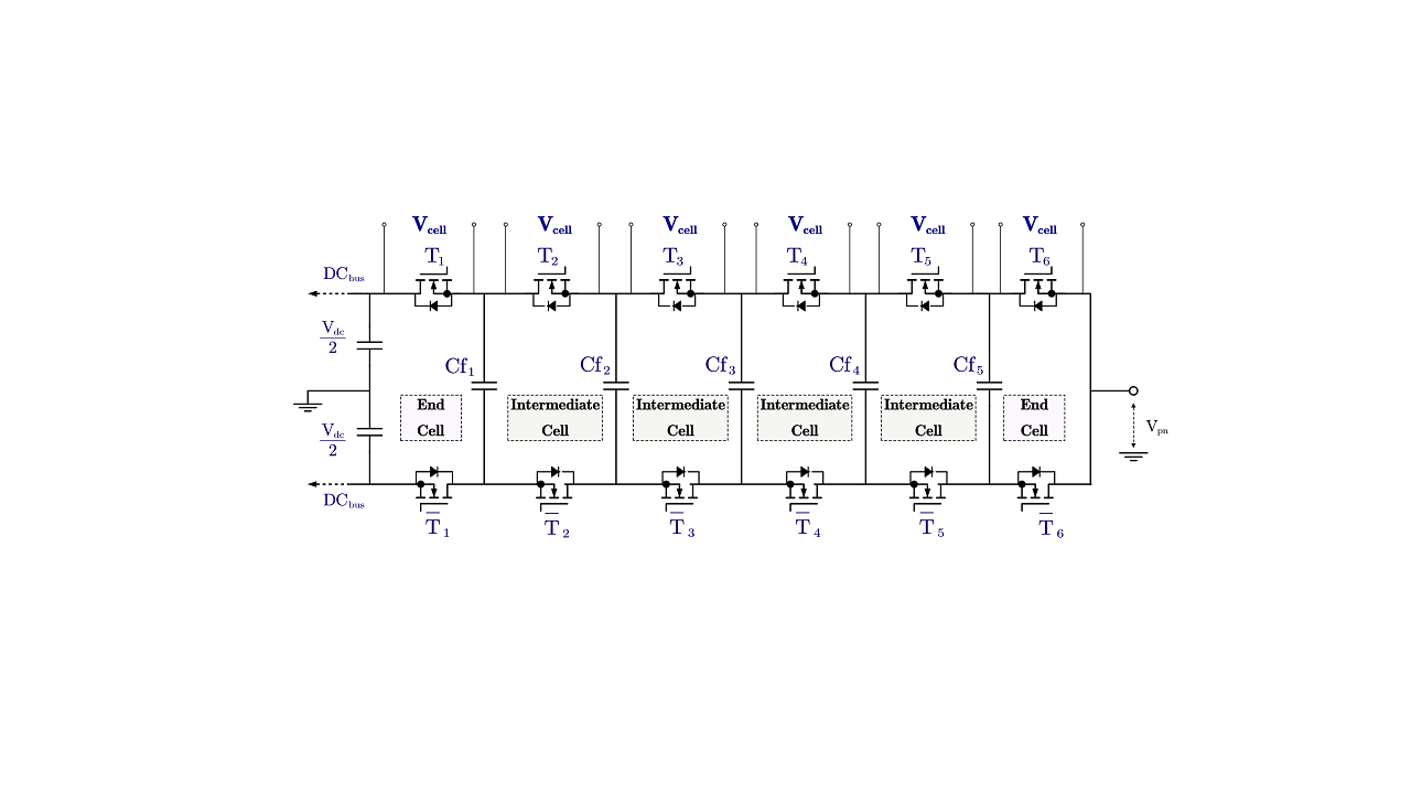
As illustrated in Fig.1, the fundamental aspect of the multicell (flying capacitor) topology is that it is composed of a network between one or two capacitors and two complimentary switches forming the structure of a cell. Therefore, the fault modes must come from a failure in one of these two components. As shown in Fig. 2, both components can fail, open or short-circuit, and this will define the converter's fault mode. The open-circuit fault (OCF) has slow dynamics and can cause overvoltage on the complimentary switch within the same cell, but this effect can be readily prevented by monitoring the capacitors' voltages and shutting down the converter. The short-circuit fault (SCF) has fast dynamics in general and the worst-case scenario happens when the fault is initiated by insulation breakdown, known as flashover fault. Lastly, the cell short-circuit fault (CSCF) happen when two switches within the same cell fail, causing the cell voltage to be zero. The surrounding cells experience voltage stress, and the failure could be propagated.
The investigation has identified the need to validate the overcurrent protection during a flashover fault to prevent a second switch failure and, therefore, avoid a subsequent cell short-circuit fault. Additionally, this work proposes a backup protection scheme for the cell short-circuit fault that clamps the voltage at the surrounding switches to prevent further damage.


