


LIBRARY
Fault Detection of Photovoltaics Panel using Impedance Measurement
Year: 2023 | Author: Jeet Panchal | Paper: H5.6
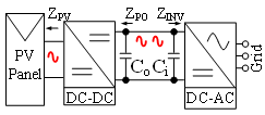
Fig.1. Small Signal Injection to PV Panel
Using power converters and inverters, a small signal is injected into the PV panel, as shown in Fig. 1, and the impedance of the PV panel is computed. The PV panel impedance under a fault condition is measured and compared using an online impedance measurement. The PV panel impedance is measured for a short-circuit fault with one PV string short-circuiting from three PV strings. Later, the PV panel impedance is measured for a hot-spot fault, in which one of the PV cells is shaded, and the bypass diode of the shaded PV cell string is removed. Fig. 2 shows the different operating points for different fault conditions in the PV panel. PV panel impedance under fault conditions is compared with the impedance under normal conditions, as shown in Fig. 2. Under the low-frequency region of the image, for the hot-spot fault, the fault indicator shows an increase in the impedance magnitude under the low-frequency region as the parallel resistance increases due to reverse characteristics of the PV cell. Under the mid-frequency region, for the hot-spot fault, the impedance phase decreases as the parallel capacitance increases for the shaded PV cell. Comparing the PV panel impedance for a short-circuit fault with a normal condition, the impedance magnitude in the low-frequency region shows a decrease in the impedance magnitude due to a decrease in the total number of PV cells, and thus the cumulative series and parallel resistance of the PV panel decreases under the short-circuit condition. This means PV panel hot-spot and short-circuit faults can be determined using online impedance measurements.
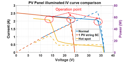
Fig.2. PV Panel Fault Detection using Online Impedance Measurement
