Fig.1. (a) SSCB implemented using the traditional MOV based VCC; (b) MOV typical I-V characteristics
Solid-state circuit breakers (SSCBs) inherently suffer from lower efficiency and are subject to the buildup of induced voltage during the interruption of non-zero fault currents flowing through the DC line inductance. As the solid-state devices themselves are limited in both their surge-energy capability as well as the available breakdown voltage rating, a voltage-clamping circuit (VCC) is often used in parallel with the solid-state branch, and is traditionally composed of metal-oxide varistors (MOVs), as seen in Fig. 1(a), to help dissipate the line energy and to clamp the device voltage to a safe value. The MOV is a highly nonlinear device, the typical I-V characteristics for which are as shown in Fig. 1(b). In the clamping region, it can conduct large currents while maintaining its peak voltage (
Vpk) within a range typically between 2x -- 3x its DC voltage rating (
VM,dc), depending on the current magnitude. This increased voltage requirement further raises on-state resistance
Ron of the main conducting path, thereby reducing the SSCB efficiency and increasing semiconductor cost.
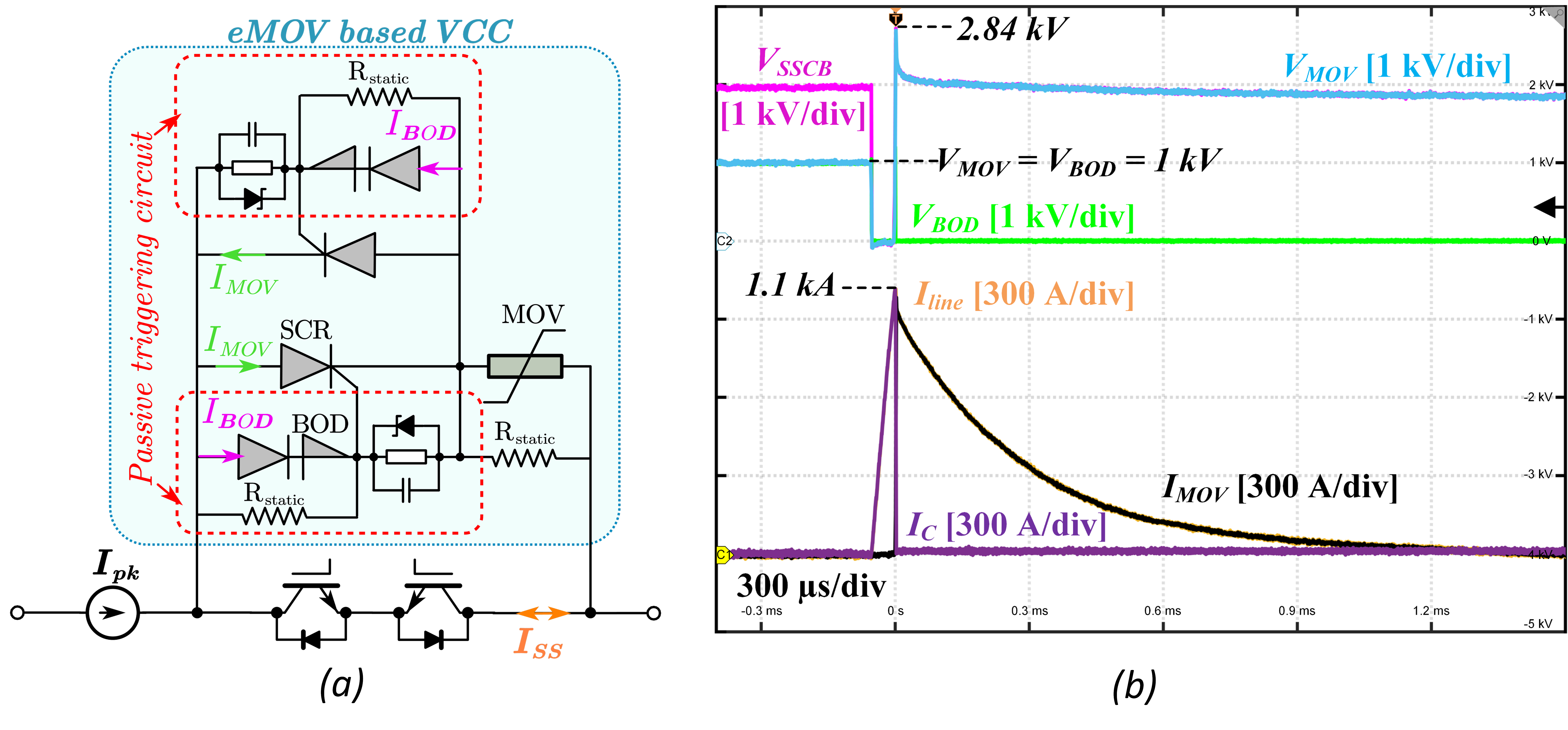
In this work, an electronic MOV (eMOV) circuit is proposed (Fig. 2 (a)) to address the drawbacks of the traditional MOV-based VCC. The eMOV uses mature thyristor technologies to provide a quasi-decoupled circuit
Vpk and system voltage
Vdc to enable the use of lower-voltage-class solid-state devices for improved efficiency. The eMOV achieves reliable fault current interruption at a lower total system cost while retaining the original clamping speed.
The proposed circuit is thoroughly analyzed, and design criteria are developed. Both standby and transient operation are successfully verified through experiments, in which a
Vpk as low as 2.84 kV is demonstrated (see Fig. 2(b)), enabling the use of a 3.3kV-class insulated gate bipolar transistor (IGBT) for a 2kV system, in contrast to a 4.5kV class device that would be required with the traditional VCC. This change could potentially reduce conduction losses by up to 30%.

Fig. 2. (a) Proposed bi-directional eMOV circuit; (b) Surge current experimental waveforms of the eMOV at 2 kV1.1 kA


