LIBRARY
A DC-Bus Planar Rogowski Coil Based Current Sensor for Half Bridge Applications

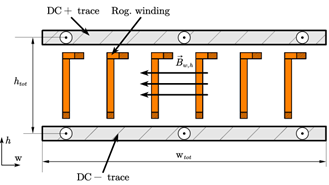
The placement of the planar Rogowski coil in between the dc- and dc+ current traces allows for the measurement of the magnetic flux density change during the switching transient. Fig. 1 depicts a possible cross-section of such a Rogowski coil integration. During a switching transient the current magnitude changes in both dc-traces and thus creates a change in magnetic flux density through the Rogowski coil windings. This allows the switch current to be measured with a Rogowski coil located on the dc-bus. Standard printed circuit board (PCB) manufacturing techniques are used for creating the Rogowski coil structure. This integration allows for a minimized sensor size and minimum sensor cost. The dc-bus length is increased by 5.6 mm to accommodate the current sensor, resulting in an increased current-commutation loop stray inductance of 399 pH while achieving a mutual inductance of 1.3 nH, which is comparable to other PCB-based Rogowski coils.

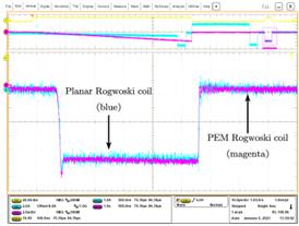
Double-pulse tests are conducted to verify the current measurement. Fig. 2 shows the switch current measurement of the designed planar Rogowski coil in comparison to a power electronics measurement (PEM) Rogowski coil. It can be observed that the planar Rogowski coil accurately measures the low-side switch current during the turn-off and turn-on switching transient.
Future work will include AC current reconstruction and short-circuit detection.


