Fig. 1. Serial half-bridge LLC converter.
Resonant converters are used extensively for voltage regulation and isolation purposes in electric vehicles. The power level and frequency of the converters are increasing with the ongoing development of wide-bandgap devices, which brings more challenges to the design of magnetic components. The first challenge is that such high power and frequency make it hard to properly utilize the Litz wire. This paper introduces a new current-sharing method for paralleled Litz wire transformers. Using this method, the transformer can withstand much higher current without increasing either cost or volume. And the power level can be further increased by integrating matrix transformers. The second challenge is integrating the resonant inductance. Different resonant inductance integration methods are summarized and compared. Controlling the leakage inductance by properly overcoming the limitations of the interleaving structure is proposed in this paper. Using this method, the desired leakage inductance can be reached without sacrificing too much winding loss. A comprehensive transformer design and optimization procedure is also presented. A 30 kW 100 kHz serial half-bridge DC-DC converter prototype is designed to verify these methods.
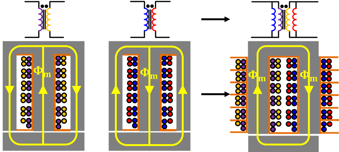
The topology of the converter is shown in Fig. 1 The input voltage ranges from 550 V to 900 V; the output voltage is from 600 V to 700 V. As shown in Fig. 2, two parallel transformers are integrated into one transformer since the flux going through the outer legs is canceled.

Fig. 2. Matrix transformer integration with flux cancellation.
Current sharing is guaranteed since the magnetic fields across the paralleled windings are the same under this symmetrical structure. A detailed mathematical analysis of current sharing will be derived in the full paper. Fig. 3 shows the transformer current waveforms with the proposed current-sharing method which is almost the same.

Fig. 3. Transfromer current waveforms


