LIBRARY
Design of Three-Level Flying Capacitor Totem Pole PFC in USB Type-C Power Delivery for Aircraft Applications

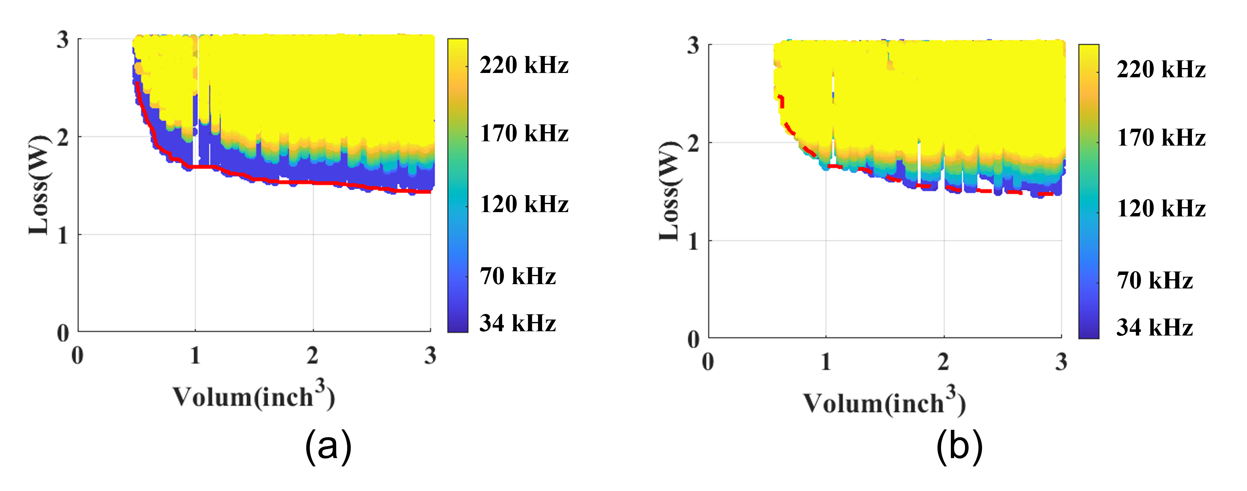
To achieve high levels of efficiency and power density, loss and volume of the semiconductor and EMI filter are optimized, as these two parts together make up most of the converter. Firstly, the PFC inductance is selected under different switching frequencies and current ripples. Then the differential-mode (DM) and common-mode (CM) filters are designed to match the EMI standard in the DO-160. Both single-stage and two-stage LC filters are considered. Different losses and sizes can be obtained with different magnetic core selections for each designed inductance. Finally, the optimum design can be observed from the total loss and volume. Optimization results with single-stage and two-stage filters are shown in Fig. 2.

Since the volumes of semiconductors and capacitors are not affected by the switching frequency and current ripple, only the volume of the PFC inductor and EMI filter are plotted in the figure. Lower-switching-frequency results stand out for the single-stage filter designs. This indicates the advantage of the single-stage filter on the volume. For the two-stage filter case, better performance of high-frequency results shows the advantage on loss. In the final optimization results, the single-stage EMI filter shows a performance level comparable to that of the two-stage filter. With low thermal stress resulting from the low switching frequency, a prototype with the single-stage filter has been designed with a total converter volume of 5.1 in3.


