


LIBRARY
Optimal Transformer Design of LLC Resonant Converters
Year: 2010
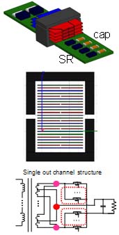
Fig. 1. Conventional transformer structure.
Conventional transformer design is shown in Fig. 1. To integrated Lm, gap is needed. In order to handle the high current, multi-PCB windings are paralleled. However, the analysis shows that this design suffers with high termination losses and high fringing flux losses. Too many layers is not preferable for manufactory.
A new transformer design is proposed in Fig. 2. The secondary side devices, SR are placed on the PCB windings. Thus, termination problem can be eliminated. Furthermore, primary side windings apply litz wire to reduce gap effect and eddy current loss. The different winding structures are studied. An optimal structure is proposed. The optimal transformer structure is proposed to achieve low loss and full integration of all magnetic components. The advantages include: (1) reduced eddy current, low ac losses for windings; (2) not sensitive to fringing flux due to gap; (3) optimal winding shape to avoid high fringing losses (4) resonant inductor and magnetizing inductor are completely integrated into the transformer (5) high efficiency and high power density.
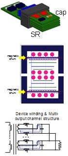
Fig. 2. Improved output transformer structure.
