LIBRARY
A Current Sharing Method for DC-DC Transformer (DCX)

The droop CS method is commonly used in DCX because of no communication bus required between the paralleled modules. This technique relies on the slope of the output regulation characteristic. CS error, the current difference between the paralleled modules, is proportional to output voltage set point error and is inversely proportional to the droop voltage. To achieve acceptable CS error of 10%, the droop voltage should be 5% of the nominal output voltage.
In traditional DCX based on open-loop resonant converter or PWM half-bridge converter, the droop voltage depends on the resistive voltage drops in the power stage, which is too small to for droop CS method. To get the required droop voltage for a specific CS error often leads to higher conduction loss.
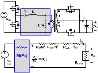
Resonant converters have a nature characteristic that the conversion gain M depends on the load current. The resonant tank behaves like a virtual droop resistance as shown in Fig.1. The droop voltage can be obtained without incurring conduction loss. One of the well-known resonant converters suitable for DCX implementation is an LLC resonant converter. However, the operating point of the LLC circuit to get the desired droop voltage is much higher than the resonant frequency, which entails the low efficiency.
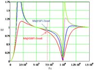
A notch filter, Lp and Cp, is introduced into the LLC resonant tank. The conversion gain M becomes more sensitive to the frequency as shown in Fig. 2. The Thus the desired droop voltage is achievable at lower frequency, which means the higher efficiency.
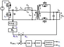
The droop characteristic is determined by the resonant tank components, so their component tolerance causes mismatch in the output regulation characteristic and worsens CS error. To make the droop characteristic insensitive to the component tolerance, the active droop control is implemented to force the output regulation characteristic to be the same. The active droop control scheme is depicted in Fig. 3. It can be derived that the output regulation characteristic is Vo=Vo(NL)-IoRD, where Vo(NL) is the no load voltage and IoRD is the droop voltage.
The converter runs at the resonant frequency at no-load and operates at above resonant frequency as the load increases. The selected operating point above the resonant frequency is also benefit the synchronous rectification. The output synchronous rectifier can be driven by the primary control signal. Currently the hardware is built to verify the concept.


