


LIBRARY
Investigation and Comparison of Cascaded H-bridge and Modular Multilevel Converter topologies for Medium Voltage Drive Applications
Year: 2014
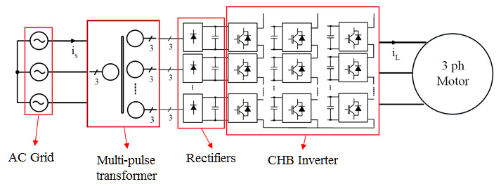
Fig. 1. Overall diagram of cascaded H-bridge converter (CHB).
Fig.1 shows that the cascaded H-bridge converter (which is also known as Robicon converter) is composed of a multi-pulse transformer, 6-pulse diode front end rectifiers with a dc link filtering capacitor, and a cell-based inverter. The design procedure must include a specified procedure for determining the values and the selection of components for each of the mentioned parts.
In a similar way, the schematic of a modular multilevel converter (MMC) is brought out in Fig. 2, where the converter is composed of a series connected half-bridge modules and arm inductances. The dc links in the case of the MMC converter can be provided by an MMC rectifier or multi-pulse rectifiers.
The aim of providing design procedure is to design converters so we can compare the con-verters to each other from as many aspects as needed. Once we have both converters in hand, we may compare them from different points of view such as: number of parts (which affects reliability), individual component rating, energy storage, efficiency, power quality, controllability, modulation requirements, control requirements and maximum available output frequency.
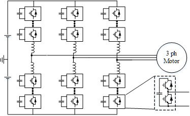
Fig. 2. Schematic diagram of modular multilevel converter (MMC).
