LIBRARY
Comparison of Coil Designs for Wireless Inductive Power Transfer

Four coil designs are surveyed and simulated using FEA software, including a circular pad, a DD-DDQ pad, a windings array, and a one-outer-loop coil. They are designed for different power levels and operating frequencies: the circular pad and DD-DDQ pad are designed for 2 kW and 20 kHz, while the windings array and one-outer-loop coil are designed for 10 W and 150 kHz. So the dimensions and percentage of materials for the coil designs are very different. To make a fair comparison normalized factors, such as power density, quality factor, and a coupling coefficient are used.
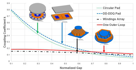
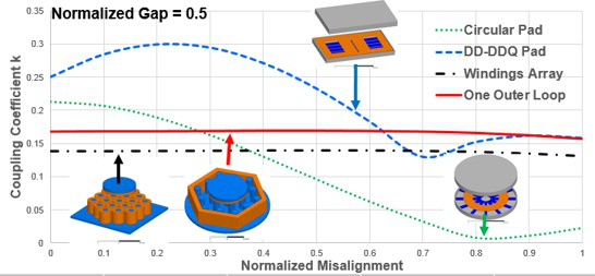
The coupling coefficient reflects the coupling between the transmitter and receiver. It will directly influence the transfer efficiency of the WIPT systems. The coupling coefficient of the four coil designs are compared with different gaps and misalignment. Fig. 1 shows a coupling coefficient vs. a normalized gap. The circular pad and the DD-DDQ pad have larger coupling coefficients when the gap between the transmitter and the receiver is small. However, when the gap is increased, the windings array and the one-outer-loop coil have larger coupling coefficients. Which structure to choose in the design process depends on the gap specification of the application. Fig. 2 shows a coupling coefficient vs. misalignment. The coupling coefficient of a circular pad drops fast with misalignment. Due to the function of a quadrature coil, the DD-DDQ pad has a coupling coefficient bigger than 0.1, but it fluctuates. The coupling coefficients of the windings array and the one-outer-loop coil are not sensitive to misalignment, because the transmitter size is bigger than the receiver. So the windings array and the one-outer-loop coil are better choices for applications where misalignment usually changes.


