


LIBRARY
Modeling and Autotuning of AVP Control with Inductor DCR Current Sensing
Year: 2014
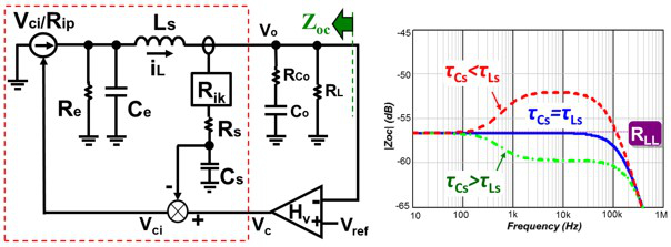
Fig. 1. Proposed Model (a) Block diagram, (b) Zoc under mismatch.
This paper first presents a new equivalent circuit model to predict the small-signal characteristic of the current-mode control with DCR current sensing accurately. The model contains an ReLsCe resonant circuit and a current source to represent the mismatch effect at high frequency, while a RsCs low-pass filter loop represents the low-frequency effect. The model shows that the closed-loop output impedance (Zoc) contains a pole-zero pair from the DCR sensor which makes Zoc away from the desired load-line resistance (RLL), so the transient response impairs.
Secondly, this paper develops a simple pole-zero compensation technique to maintain a constant output impedance and a fast transient under possible mismatch conditions, so the output capacitor can be minimized with a simpler autotuning circuit on the VR controller. The idea is adding a simple and easy-integrated compensator (HCom) along the current feed-back path to create an adjustable pole-zero pair to correct the output impedance close to RLL.
The proposed autotuning configuration in Fig. 2 contains Hcom with a high-pass filter (RC) and a variable gain amplifier (A), and a Vo slope detector. When a step-up load transient event is identified at Vi', HCom is adjusted gradually based on sensed dVo/dt, because Zoc can be estimated by sensing dVo/dt. When Zoc
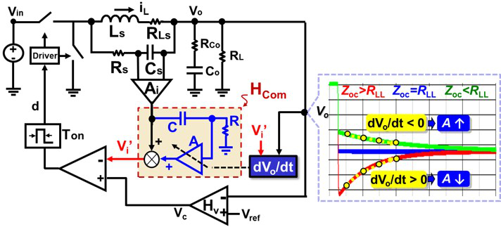
Fig. 2. Block diagram of proposed autotuning configuration.
