LIBRARY
State-trajectory Control of LLC Converter Implemented by Microcontroller

State-trajectory control functions have been discussed and verified separately. However, in real applications, all these functions need to be realized in one single controller. Therefore, it is worthwhile to determine how to implement all state-trajectory control functions in one controller. There are mainly three challenges to achieve this goal: firstly, complex calculation in state-trajectory control requires a high-performance digital controller, such as a high-end FPGA and a very fast analog-to-digital converter; however, the cost-effective MCU is preferred in industrial applications; secondly, burst-mode control with constant burst-on time and optimal switch patterns can't be used directly when associated with normal operation, because there would be very large dynamic oscillation in both the resonant tank and output voltage during the transient processes between burst mode and normal operation; thirdly, for a given application, it is still unknown how to design the whole control system structure and then select a proper MCU.
To solve these problems, a simplified calculation process is proposed for the SOTC to minimize digital delay. The proposed guidelines to select a proper microcontroller limit calculation delay and ADC delay to within one switching cycle to ensure good transient performance. Optimized transient processes are proposed that eliminate large oscillation between burst mode and normal operation. Soft start-up is implemented by sensing the output voltage only.
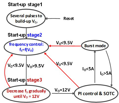
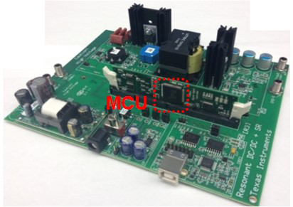
After implementing each control function by MCU, all the control functions are integrated within one cost-effective MCU. The state transition diagram of the whole system is shown in Fig. 1. Experimental results are demonstrated on a platform, as shown in Fig. 2, which is a 130kHz 300W 380V/12V half-bridge LLC resonant converter with MCU TMS320F2808.


