LIBRARY
High Reliability Capacitor Bank Design for Modular Multilevel Converters in MV Applications

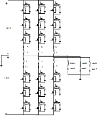
In Fig. 1 A and B, the modular multilevel converter is shown along with each module for each of its three arms, respectively. The DC-link capacitor for the power converters can be described using equations (1), (2) and (3), in which VCPerArm is the voltage of the capacitors per arm, CPerArmMin is minimum total capacitor value of the arm, and tVmaxis the time interval of the voltage ripple.
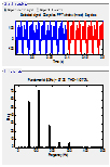
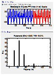
Considering reliability and life time based on (2), the practical floating DC-Link capacitor bank is designed. Because of the design of the DC-link capacitor, usually two types of capacitor are used: aluminum electrolytic capacitors and film capacitors. Three design examples for the floating DC link capacitor are carried out to investigate the practical design issues of the capacitor bank using aluminum electrolytic and film capacitors. These three design examples are simulated, as shown in Fig. 2. The values of the capacitance in each case, which are greater than the minimum required capacitor value for the specific ripple, are shown in Table 1. For each case, three design examples are created using Cornell Dubilier aluminum electrolytic capacitors, Cornell Dubilier film capacitors, and Electronicon film capacitors.
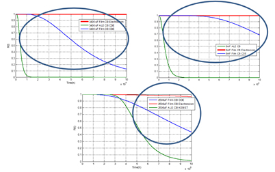
The reliability equation of the each design example in each cases are obtained and shown in Fig. 3. The failure rate of each capacitor is calculated based on the datasheets, which are provided by the manufacturer.
The result shows that in each case the design based on the film capacitor has a longer life and higher reliability than the design based on the aluminum electrolytic capacitor.
In order to increase the reliability of the aluminum electrolytic capacitor, we present the novel idea of the adding the film capacitor to the aluminum electrolytic capacitor to enhance the life time and reliability of the capacitor bank.


