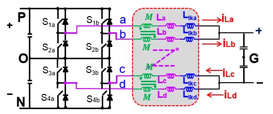
Fig. 1. 3-level DC/DC Converter with Integrated Coupled Inductor
This paper investigates a multi-level approach to increase both voltage and power ratings of DC/DC converters with a paralleled phase legs configuration for renewable energy systems. And one two phase paralleled, three-level DC/DC converter was built to work with DC/AC stage and handle 200kW power rating with 20kHz working frequency. By applying a coupled inductor the circulating current caused by interleaving modulation between two phase legs can be suppressed and inductor current ripple is small. And the two separated coupled inductor in the converter can be further integrated as one. With one integrated coupled inductor, as shown in Fig.1, the power density can be further increased to compare with the conventional coupled inductor case. Based on the flux analysis of the integrated coupled inductor, the mathematical model of integrated coupled inductor can be defined first. By mapping the mathematical model into circuit, the circuit model can be built. As shown in Fig.2, six mutual inductances are used to represent different coupling effects between converter arms, and four single inductance are applied to represent the leakage flux in each arm of the converter. Here, M
ab and M
cd represent the negative coupling between arm a and arm b, and between arm c and arm d, respectively. M
ac, M
ad, M
bc, M
bd represent the positive cou-pling between arm a, b, c and d. And such positive coupling is designed to further reduce the output current ripple. For the paralleled phase legs, the model can be built with the concept of three-terminal switch easily. By combing the model of paralleled phase legs with the model of integrated coupled inductor, one can have a complete model of this converter for control loop design.
This paper also gives and analyzes on the modeling of such converter under symmetrical parameters assumption. With this assumption, the control-to-output transfer function is a second-order one. By further neglecting all the parasitic in the circuit, one can find that the control-to-output transfer function has a similar form comparing with conventional buck converter. M
ab and M
cd don't show up the in transfer function, which means that the negative coupling effect won't affect transient response under symmetrical parameters assumption. With control-to-output transfer function, both current loop and voltage loop control can be designed and simulation results are given.
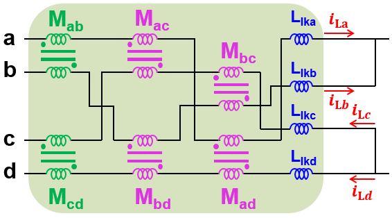
Fig. 2. Model of Integrated Coupled Inductor


