Become a Member
Become a Member

LIBRARY

LCL Filter Design and Inductor Current Ripple Analysis for 3-level NPC Grid Inter-face Converter

Year: 2015
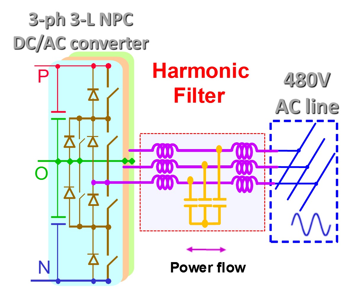
Fig. 1. . 3-level NPC converter with LCL filter
The harmonic filter for a 3-level neutral point clamped (NPC) grid interface converter is designed with good filtering performance and small component size. Different filter topologies are evaluated, and the LCL topology is selected because of the attenuation and size tradeoff. The basic design procedure and guideline for the LCL filter is introduced first. The design of the inverter side inductor L1 is emphasized due to its cost. A detailed inductor current ripple analysis is given based on the space vector modulation (SVM). The analysis derives the inductor volt-second and the maximum current ripple equation in the line cycle. The analytical expression for the maximum inductor current ripple is established with the analysis. It also reveals the switching cycle and current ripple distribution over a line cycle, including the power factor consideration. The total system loss is calculated with a different ripple current, and inductor L1 is determined by the loss and size tradeoff.

The capacitor and grid side inductor L2 is designed based on the attenuation requirement and the reactive power consumption. The grid code harmonic and the inverter output voltage spectrum together setup the attenuation requirement for the LCL filter. The L2 inductance is designed to meet that requirement. Finally, the resonant peak of the LCL filter is considered with the passive damping circuit. Different damping circuit topologies for the LCL filter are compared and investigated in detail. The RLC damping circuit is selected based on the damping result, component size, and the power loss. The filter design is verified by both simulation and a 200kVA 3-level NPC converter hardware.

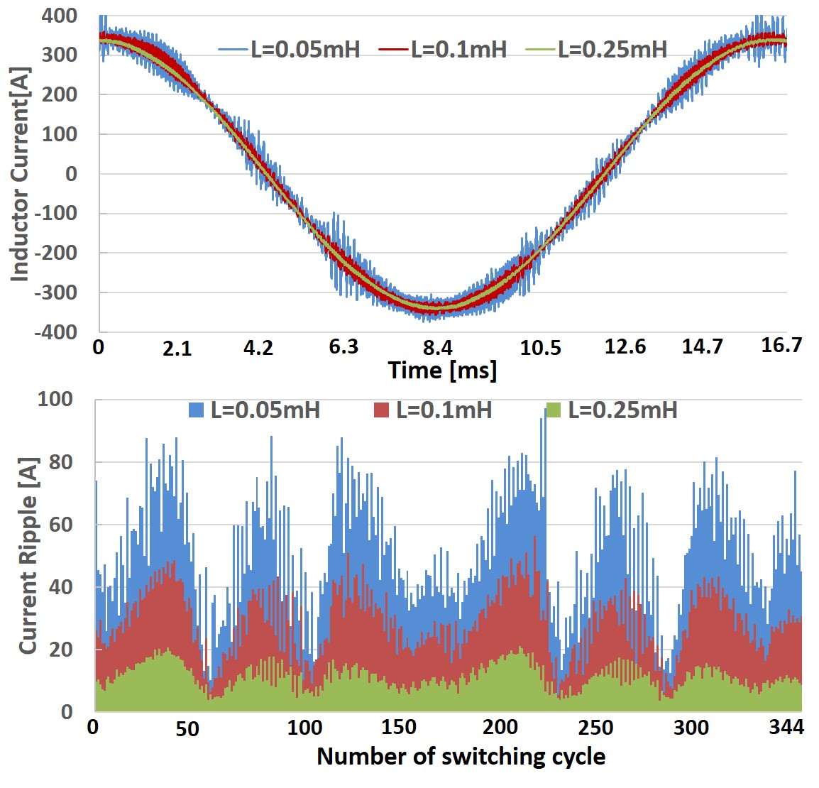
Fig. 2. Inverter side current ripple waveform

Our Industry Partners