


LIBRARY
Small-Signal Analysis and Optimal Design of Constant Frequency V2 Control
Year: 2016
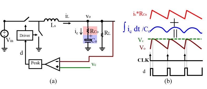
Fig. 1. Constant frequency V2 peak control (a) circuit diagram; (b) steadystate waveform.
First the case with no external ramp is considered, and the analysis shows that there are two kinds of sidebands that can be decoupled; inductor current sidebands cause one pair of double poles, and capacitor voltage sidebands cause another pair of double poles. To avoid the coupling and interacting of these sidebands, two factors should be considered; the duty ratio (D) and the current feedback strength (). For different types of capacitors there are different stable regions that can be considered based on switching frequency, as shown in Fig. 2. With the addition of an external ramp, it was found that for the OSCON capacitor, the stability region can be extended to cover the whole duty cycle region with the appropriate selection of external ramp, as shown in Fig. 3.
For ceramic capacitors, the external ramp is not sufficient for stable operation. Therefore, a hybrid ramp strategy is proposed for the optimum design purposes; a current ramp is used to enhance the current strength feedback to minimize the effect of the capacitor voltage feedback loop, while an external ramp is used to reduce the sample and hold effect for the inductor current feedback loop. Either inductor current or capacitor current can be used to enhance current feedback strength for the ceramic capacitor case. As shown in Fig. 4, a well-damped system can be achieved with a hybrid ramp.
The proposed hybrid ramp method was experimentally verified for the ceramic capacitor case, as shown in Fig. 5, where the analytical model agrees with the experimental results.
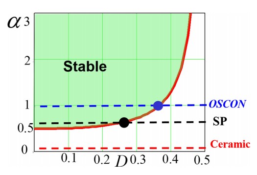
Fig. 2. Stability criterion of constant frequency V2 peak control with Fsw =300 kHz.
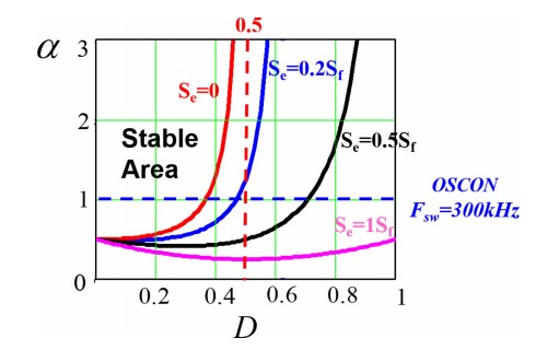
Fig. 3. Diagram of stability criterion with external ramp compensation.
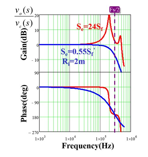
Fig. 4. Control-to-output transfer function: (red) without hybrid ramp (blue) with hybrid current ramp
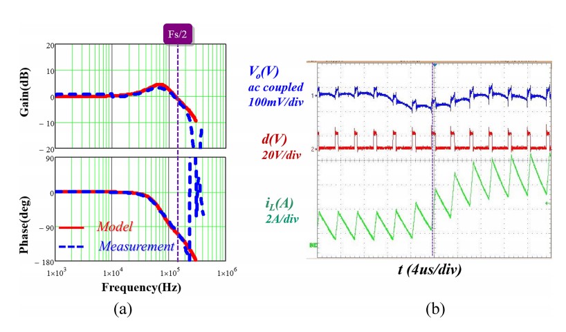
Fig. 5. Experimental results for ceramic capacitors with hybrid ramp compensation. (a) Control-to-output voltage transfer function (b) Load transient step-up
