LIBRARY
Two Core Implementations of Coupled Inductors for Paralleled Three-phase Power Converters

This paper presents a new structure for coupled inductors in three-phase converters that min-imizes the weight of the magnetics in paralleled converters. In the steady state, every current harmonic at each frequency can be classified into one of four groups according to DM and CM, and phase-shifted by 180, as shown in Table 1. Coupled inductors provide large impedance only for circulating currents, which are in Groups 3 and 4.
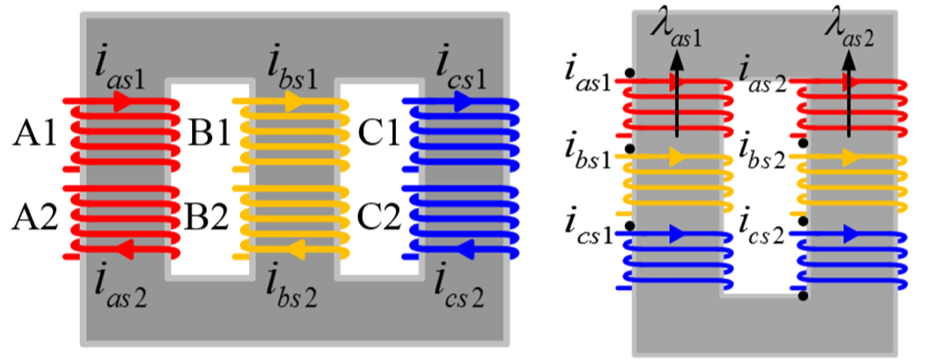
The proposed coupled inductors are comprised of two cores. One core is for use in DM coupled inductors (DMCIs) to suppress the DM circulating harmonics of Group 3. The other core is a CM coupled inductor (CMCI) to suppress the CM circulating harmonics of Group 4. By combining the structure of a conventional three-phase inductor with the coupled inductors, a single E-core with six windings, as shown in the left of Fig 2, can be implemented to suppress DM circulating current. By combining the structure of the CM choke with the coupled inductors, a U-core pair with six windings, as shown in the right of Fig. 2, can effectively couple the flux of the CM circulating current.
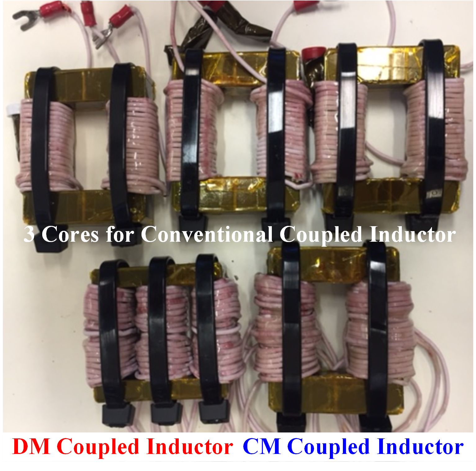
Prototypes have been built to examine possible size reduction. Conventional coupled inductors and the proposed DMCI and CMCI are designed to have similar maximum magnetic-flux density, while the turns number for each coupled inductor is set to have a mutual inductance value. Using the proposed integration can reduce the weight of the coupled inductor by 30%, from 510g to 361.5g, with the same attenuation for circulating current.


