


LIBRARY
Equivalent Electric Circuit for a wave energy converter
Year: 2017 | Author: Chien-an Chen | Paper: D2.1
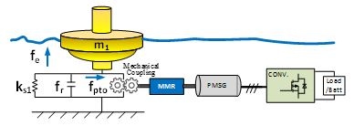
Fig. 1 Mechanical Diagram of WEC system including: Buoy, MMR, Mechanical Coupling, Generator, and Power Converter.
Through approximation and circuit synthesis methods, wave-buoy behavior can be linearized as a RLC circuit network in Fig 2. The nonlinearity of MMR sets can be modeled as transformers and diodes. Along with a generator circuit model and power converter, a general methodology is shown to convert a multidisciplinary system into electrical components, which can be an aid to the electrical designers in the wave energy area.
Two applications will be introduced in this work. One is to apply a reliability analysis of each component. Under irregular wave conditions, a wave force is modeled as a current source that defines the input of the system in Fig. 2. Each rotational speed and torque values can be monitored real-time as voltage and current waveforms, so the maximum stress of each component can be recorded. Another is applied to optimize the systems output power. Based on an equivalent circuit, the system's output power capability can, thus be analyzed under different wave periods and gear ratio in Fig. 3.
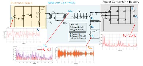
Fig. 2 Equivalent circuit of the WEC and its output waveforms under irregular wave condition.
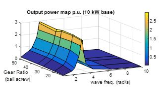
Fig. 3 Application of Equivalent Circuit for maximum output power under different wave frequency and gear ratio.
