LIBRARY
Stability Criterion of Droop-Controlled Parallel Inverters Based on Terminal Characteristics of Individual Inverters

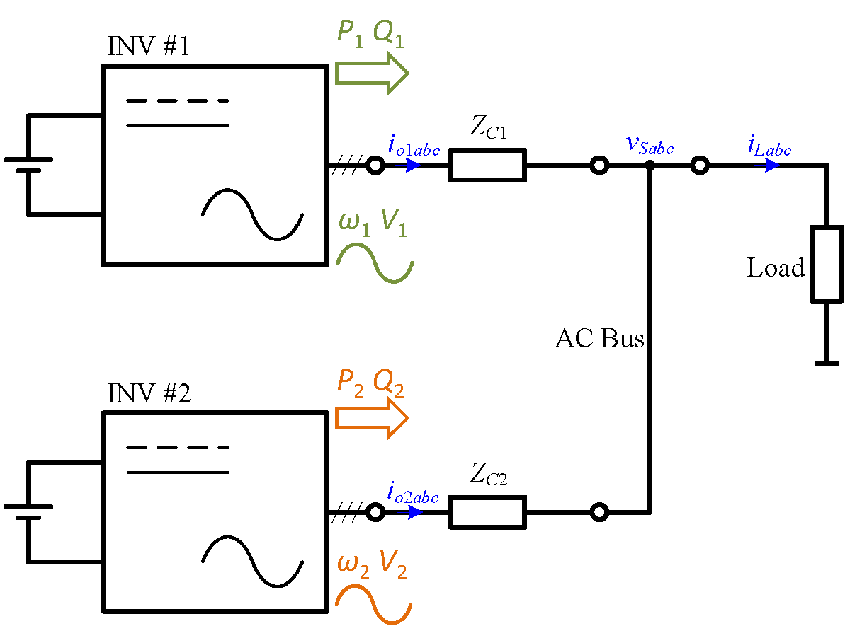
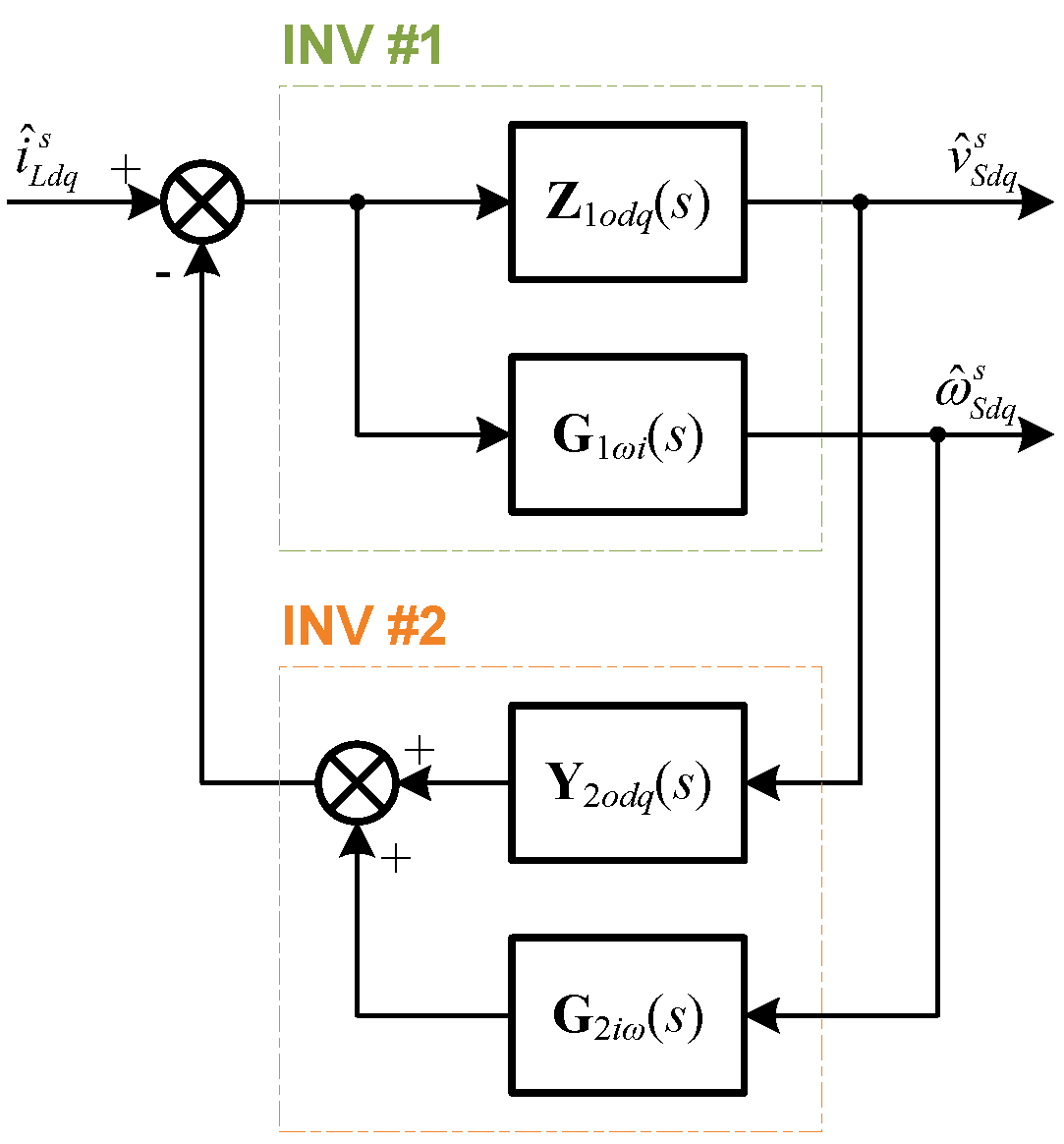
To overcome this problem, this paper proposes a stability analysis approach for the droop-controlled parallel inverters based on the terminal characteristics of individual inverters. At the beginning, the terminal characteristics of individual inverters with droop control are defined in the system synchronous reference frame (SRF), which can be represented by the transfer function be-tween the output current and output voltage, and the transfer function between the output current and fundamental angular frequency. Then, the terminal characteristics of the whole parallel system are derived, including the characteristics of each individual inverter. Furthermore, a stability crite-rion is proposed for the parallel inverters based on the terminal characteristics of each individual inverter according to the Generalized Nyquist Criterion. Finally, the proposed terminal characteris-tics and stability criterion for droop-controlled parallel inverters are verified in the frequency domain.


