LIBRARY
Design of GaN-based MHz Totem-pole PFC Rectifier

The cascode GaN HEMT is applied in the totem-pole PFC rectifier while pushing the operating frequency to above 1MHz. Several important issues, which are less significant at low frequencies, are emphasized at high frequencies, and corresponding solutions are proposed and experimentally verified.
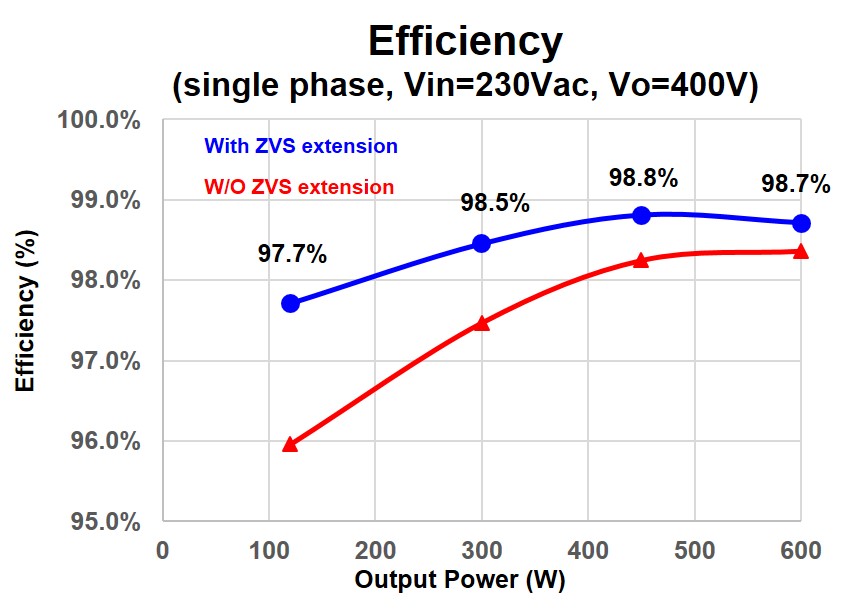
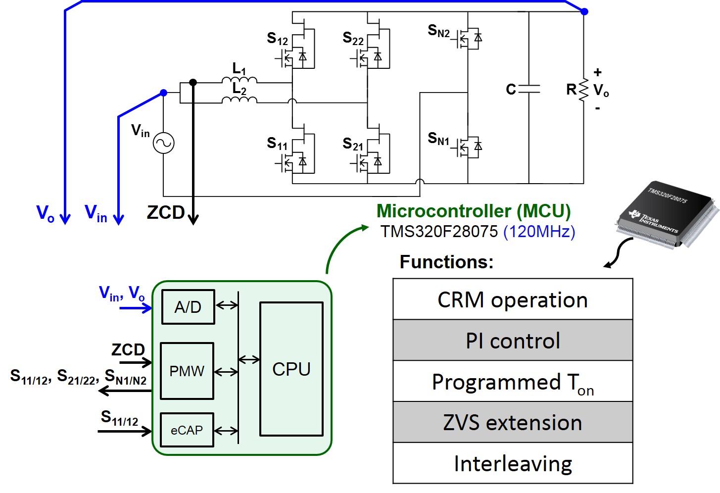
In this research, the advantages of the totem-pole PFC rectifier are summarized at first, while the differences between hard-switching and soft-switching and between the Si MOSFET, and the GaN HEMT are illustrated in second. After that, detailed design considerations are presented, including the ZVS extension to solve the problem of switching loss caused by non-ZVS valley switching; variable on-time control to improve the power factor, particularly the zero-crossing distortion caused by traditional constant on-time control; and interleaving control to cancel the input current ripple. The volume of the DM filter is reduced significantly by pushing the operating frequency to several MHz and the use of multi-phase interleaving.
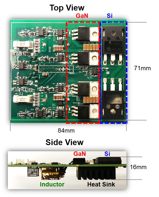
A 1.2kW two phase interleaved totem-pole PFC prototype is demonstrated with 220W/in3 power density and 99% efficiency. All proposed functions with closed-loop control are implemented by a 120MHz MCU.


