


LIBRARY
10 KW Transformer and DC Stage Design for Electrical Vehicle Charging System
Year: 2017 | Author: Xingye Liu | Paper: D4.8
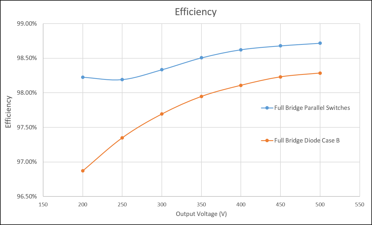
Fig. 1. Efficiency comparison
When designing the converter operation mode, in order to regulate the output voltage, the opera-tion frequency range should be below the resonant frequency so a high gain can be achieved without any additional loss. In this range there is no secondary side switching loss, and the pri-mary switches' turn-off loss can be minimized as well. Peak current and RMS current are com-pared for different resonant frequencies, and the final operation range is selected to be 200 KHz to 400 KHz.
The transformer design is based on this frequency range. Because the switches (or diodes) can create a great deal of power loss, the transformer should have a better performance as it will determine the whole converter's power density. Ferrite 3C97 is selected as the material for this operation range, and the first prototype is designed by first limiting the loss. The volume is still large, and further efforts will be made to design a better high-power-density transformer.
The first LLC converter with open-loop control will be tested, and more work will be done on transformer design. Either a matrix transformer or a planar structure will be studied as well.
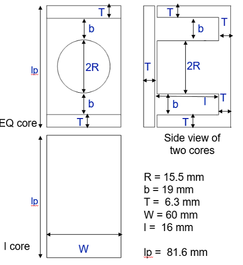
Fig. 2. Core design overview
