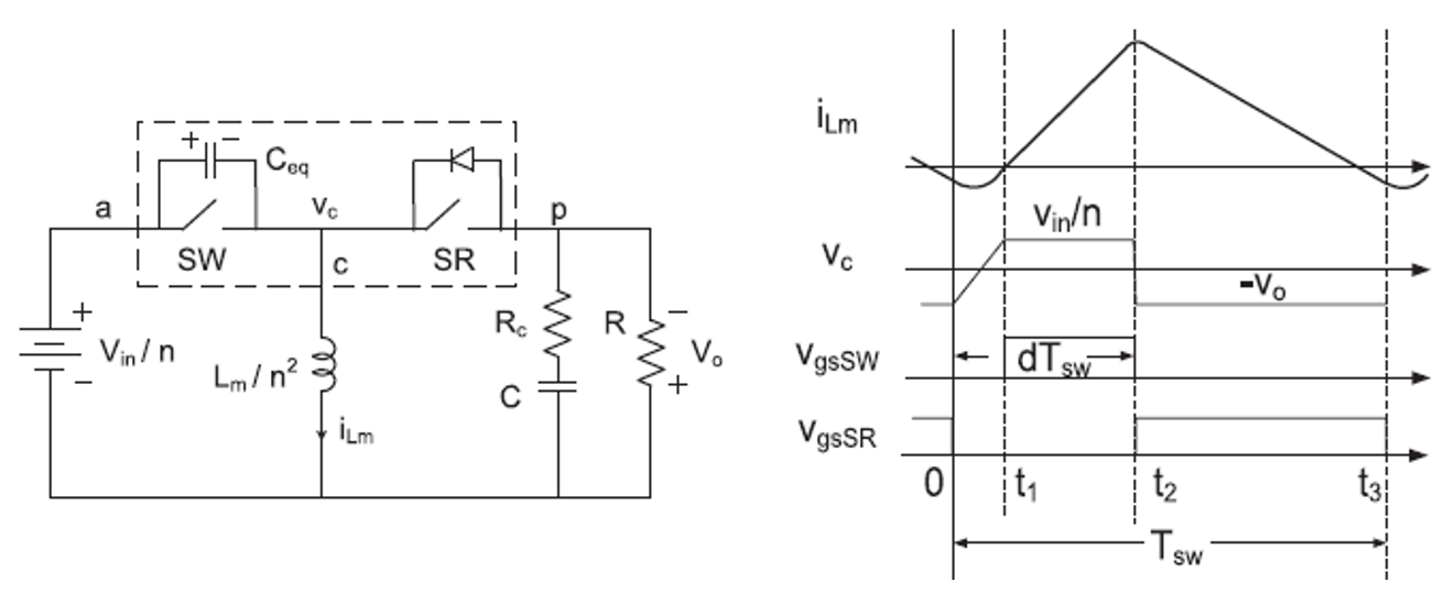
A modified small signal model is depicted in this section to address the double-pole splitting phenomenon for a quasi-square-wave (QSW) flyback converter. The methods used here are also applicable for other QSW converters. To simplify the analysis, the components on the primary side of the flyback converter are transferred to the secondary side with respect to the turns ratio, which is equivalent to the buck-boost converter shown in Fig. 1. The leakage inductance is in series with the magnetizing inductance. Since the coupling of a transformer is easily greater than 97 percent in practice, this leakage inductance is negligible. The functional block represents the total nonlinearity in these converters, and is shown as a three-terminal nonlinear device. The terminal designations a, p, and c refer to active, passive, and common, respectively. The equivalent capacitance, C
eq, is the sum of the output capacitance of SW and SR.
A modified circuit-oriented, small signal model of a QSW flyback converter is proposed. The model is successfully demonstrated to analyze the damping effect of the resonant time on system double poles. When the resonant time goes longer, the double poles split further. It is verified by simulation in Simplis and experiments with a 5 MHz QSW flyback converter. With the help of the proposed small signal model, the transient performance is improved significantly with high loop bandwidth.

Fig. 1. (a) Schematic of QSW buck-boost converter and (b) typical waveforms.

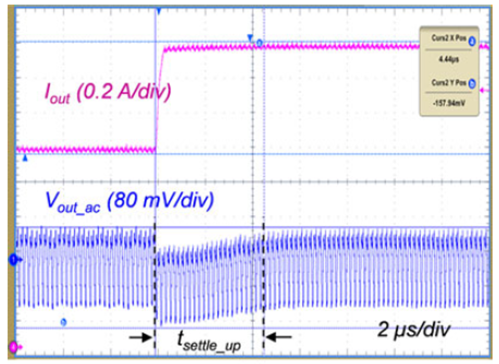
Fig. 2. Load step-up response for QSW flyback converter with crossover frequency of 260k Hz.


