LIBRARY
Modeling and Control for 48V/1V Sigma Converter for Very Fast Transient Response

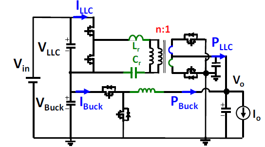
pology as shown in Fig. 1, an outstanding performance in terms of efficiency (95.2%) and power density (700 W/in3) has been demon- strated. Both the efficiency and power density are much higher than state-of-art solutions. However, the modeling and control of the Sigma converter is challenging due to the quasi-parallel structure, and they have not been solved properly yet. The small-signal model of current mode and V2 control are provided and compared with voltage mode control. The V2 control with active droop control is chosen for high-bandwidth and constant load line design.
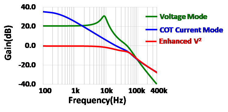
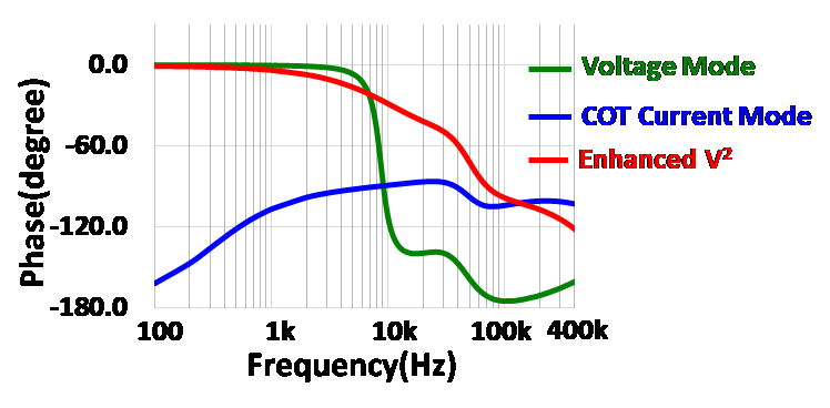
Fig. 2 shows the bode plot of constant-on-time current mode and enhanced V2 control, as well as the comparison with volt- age mode control, where Vin=54 V, Vo=1.4 V, D=0.07, n=12, Lr=440 nH, L=210 nH, Cin=10 uF, and Co=2 mF. From Fig. 3, voltage mode has a low frequency double pole, and COT current mode has a low frequency RHP pole (gain decreases and phase increases). As a result, both voltage mode and COT current mode are not suitable for high bandwidth design, and enhanced V2 control is chosen.
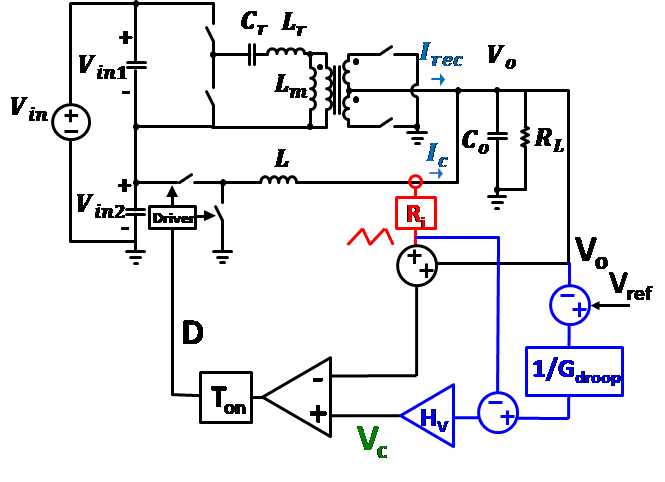
It is well known that CPU VR must achieve adaptive voltage positioning (AVP) to meet Intel load line specifications. In order to meet the AVP requirement, the active droop control scheme is ad- opted, as shown in Fig. 3. With this method, the simulation results of output impedance with different operating points is shown in Fig. 4. Constant load line is achieved at all operating regions.


