LIBRARY
Transmitter Coil Design for Free Positioning Omnidirectional Wireless Power Transfer System

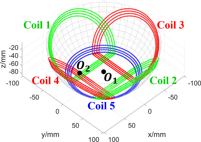
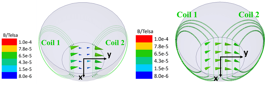
To generate an omnidirectional field, a novel transmitter coil structure in a charging bowl shape is proposed (Fig. 1). There are five coils: coils 1-4 are wound from the bottom to the side face of the bowl; coil 5 is placed around the bottom of the bowl. The magnetic field induced by coil 1 and coil 2 at the base of bowl is mainly in the y direction, as shown in Fig. 2(a). Symmetrically, the magnetic field induced by coil 3 and coil 4 is mainly in the x direction at the bottom of the bowl. The magnetic field induced by coil 5 is mainly in the z direction. With the x, y, and z direction magnetic field at the base, the magnetic field can rotate in different directions with modulated excitation current.
As shown in Fig. 2(a), the magnetic field induced by coil 1 and coil 2 is not uniform. Therefore, the power transfer decreases when there is some misalignment between the transmitter coil and receiver coil. To resolve this issue, the transmitter coil geometry is optimized to achieve strong, uniform coupling distribution. Normally, finite element analysis software is utilized to get magnetic field distribution, but it is time consuming and not suitable for optimization. Therefore, an analytical model to calculate magnetic field distribution based on the Biot-Savart law is built in this paper. The parameter optimization is implemented in MATLAB with a genetic algorithm function. The magnetic field distribution with the optimized coil geometry is shown in Fig. 2(b). Compared with Fig. 2(a), the magnetic field is much uniform after the coil optimization. There are free-positioning characteristics for receiver devices in our WPT system.


