Become a Member
Become a Member

LIBRARY

Evaluation and control of active capacitor banks for a floating power modules based converter

Year: 2020 | Author: Tam Nguyen | Paper: T4.12
Converter schematic
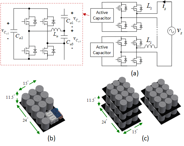
Fig. 1. (a) PIU with active capacitor banks, (b) assembly of one active capacitor, and (c) assembly of an equivalent capacitor bank
  With multiple converters connected to a power grid, the problem of instability may arise. An impedance measurement unit (IMU) is utilized as a tool to measure the system impedance to analyze its stability. A perturbation injection unit (PIU) inside the IMU injects perturbations to the grid. The voltage and current responses are then measured, and impedance is calcu- lated accordingly. Unlike a traditional rectifier, the PIU application is more complex, with multiple current harmonics. The injection frequency, which is nearest to the grid frequency, causes the largest ripple on the dc-link voltage. In order to reduce the voltage ripple, a large capacitor can be connected in parallel with the dc-bus of the PIU. In this paper, the active capacitor is utilized as a high-power-density solution to replace the passive capacitor in the PIU. The active capacitor consists of one full bridge, one inductor, and three film capacitors, and is connected in parallel with a floating H-bridge, as illustrated in Fig. 1(a). A control scheme is proposed as in Fig. 2(a) to compensate multiple power harmonics and balance the dc-link voltage in the active capacitor. The controlled voltage of the active capacitor’s full bridge is expressed as Fig. 3, where &Delta&lparvCa1&lpar t&rpar&rpar is the ripple extracted from the voltage vCa1&lpar t&rpar, &Delta&lparvCa1&lpart&rpar&rpar&VerticalSeperator&omegas&plus&omegap is the ripple component of &Delta&lparvCa1&lpart&rpar&rpar at &omegas&plus&omegap, and &beta is the
loss compensation factor, which is multiplied with the derivative of &Delta&lparvCa1&lpart&rpar&rpar&VerticalSeperator&omegas&plus&omegap to balance vCa2.
  Simulation results of a three H-bridges based PIU are provided to verify the effectiveness of the active capacitor solution. The voltage waveforms across Ca1, Ca2, Ca3 and dc-bus voltage are included in Fig. 2(b). It is seen that the voltage vCa3, which is generated by the full bridge of the active capacitor, follows the voltage -&Delta&lparvCa1&rpar as well. Since each dc-link voltage is the sum of vCa1 and vCa3, its value is maintained constant around 1,000 V with a small ripple. All the dc-bus ripples of the three floating H-bridges are limited within 4&percnt the dc-bus voltage.
  Fig. 1(b) and 1(c) show the assembly of the active capacitor and an equivalent capacitor bank, respectively. The comparison indicates that with a 5&percnt DC-bus ripple requirement the active capacitor solu- tion for the PIU helps reduce both the volume and weight by five times over the traditional passive capacitor solution.
Control scheme
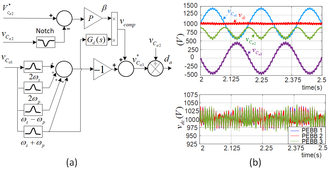
Fig. 2. (a) Proposed voltage-mode control scheme, and (b) simulation results

Equation
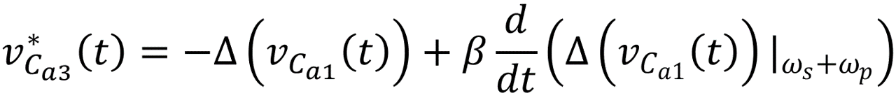
Fig. 3 Controlled voltage of the active capacitor’s full bridge

Our Industry Partners