RESEARCH
Control Technique for High-Frequency Soft-Switching Three-Phase Inverter Under Grid Fault Condition

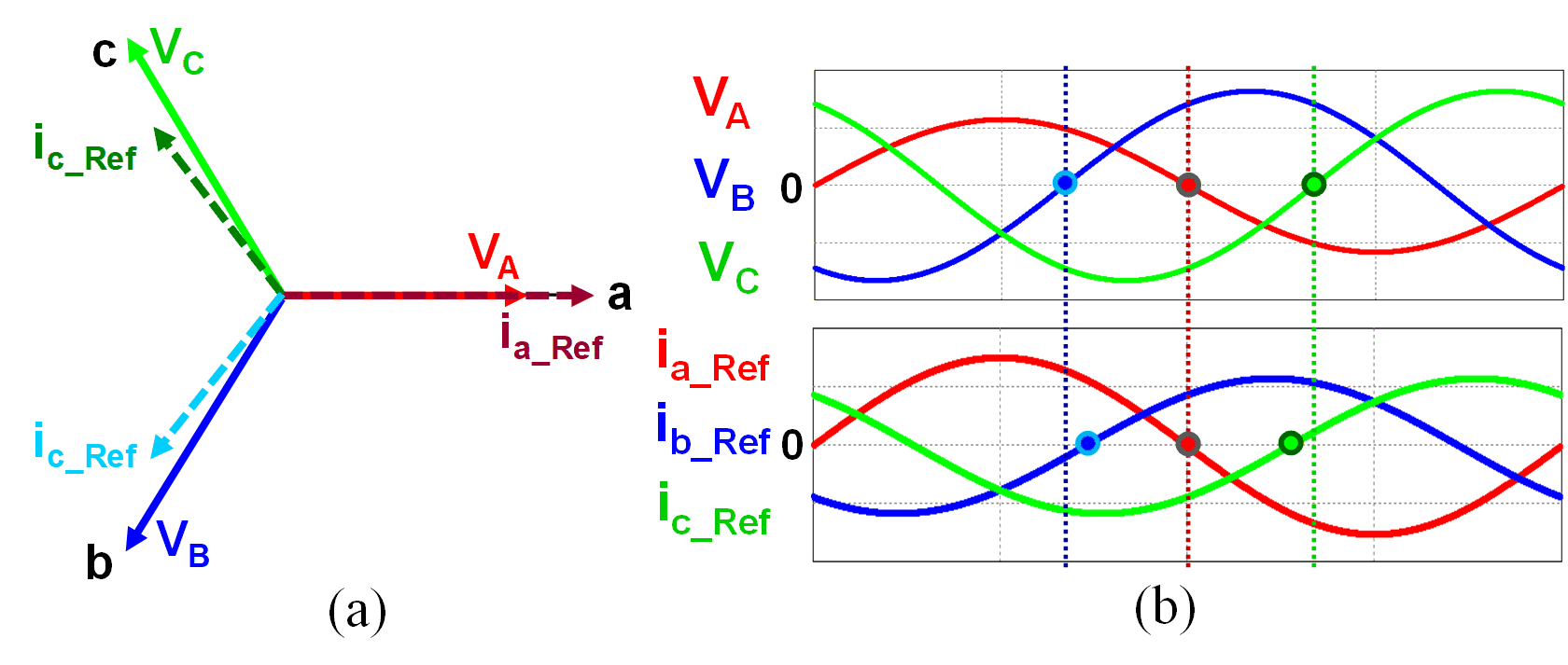
Voltage sag is one of the most frequently happening grid faults. Under this condition, the magnitude of 3-phase voltage drops and imbalance appears. This could cause oscillation in the active power at the output side which is reflected to the dc-link capacitor as a larger voltage ripple. The voltage ripple across the dc-link capacitor may lead to over-voltage protection and stop inverter operation. To avoid such situations, constant active power should be delivered to the grid. For constant active power delivery, the output current to the grid becomes unbalanced as shown in Fig.1.
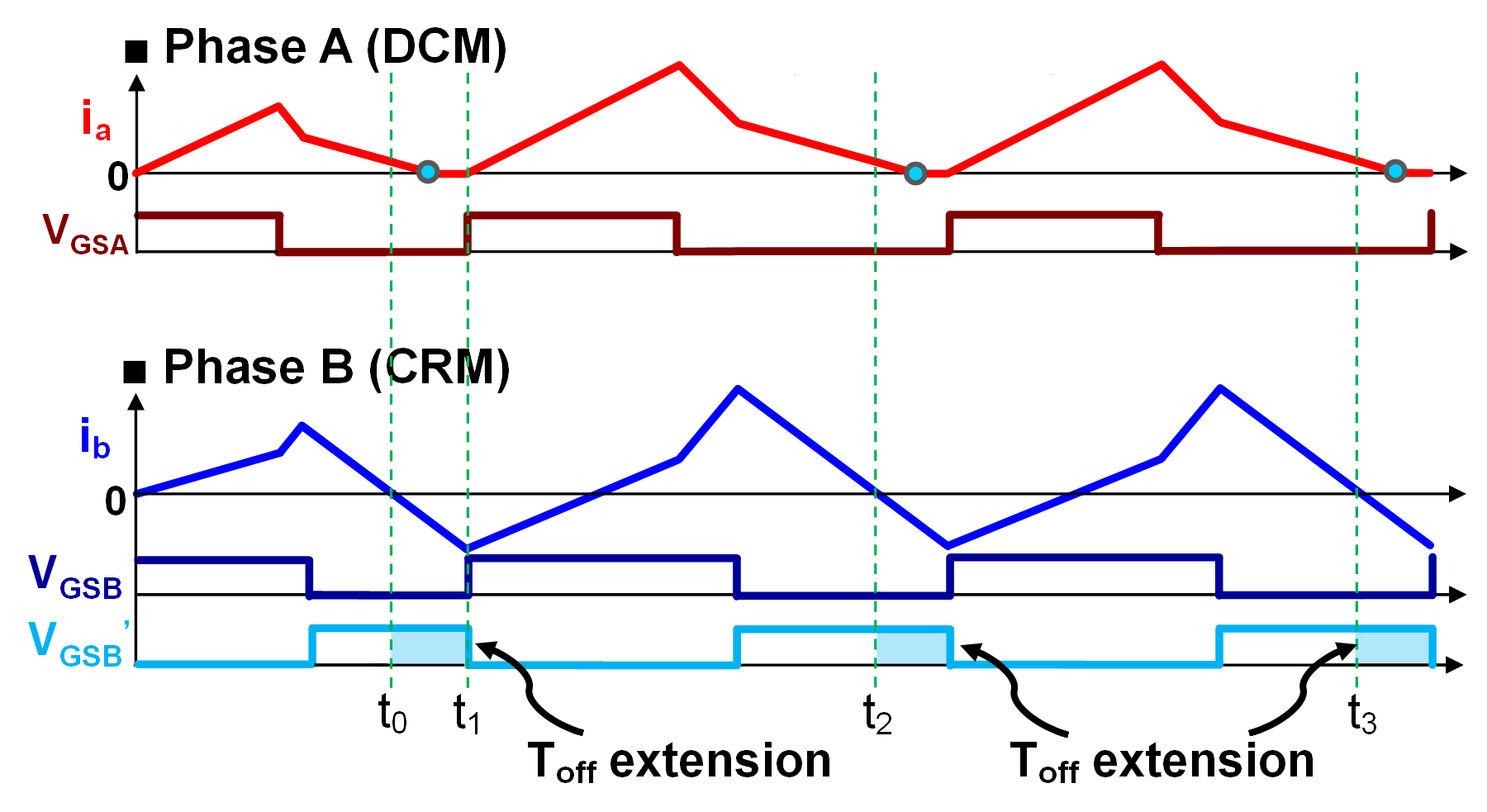
The challenge is to maintain the soft-switching during the grid fault. However, CCM operation occurs where DCM operation is intended. As a result, turn-on loss of the inverter increases substantially. Due to the unbalanced grid voltage and the ac current reference, the CRM phase current reference is smaller than DCM phase current reference in some region, which never happens under balanced grid conditions. In this case, since the CRM phase determines the turn-on instant, the DCM phase is turned on before the DCM phase inductor current reaches zero losing volt-sec balance.
To prevent the CCM operation and reduce the turn- on loss, off-time extension is used in the CRM phase as illustrated in Fig. 2. By comparing zero current detection (ZCD) signals of CRM phase and DCM phase, decision- making for off-time is made. In this control technique, CRM phase off-time is extended until DCM phase current reaches zero. Consequently, the concentrated turn-on loss in CCM operation region diminishes significantly.


