RESEARCH
Multi-Step Simplified Optimal Trajectory Control (SOTC) for LLC Resonant Converter

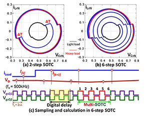
In this paper, first, implementation of SOTC is optimized and can be applied to the LLC converter with a maximum switching frequency of 250kHz with 60MHz MCU. To further improve switching frequency, multi-step SOTC is proposed to apply a low-cost MCU to a high frequency LLC converter. The basic concept is that instead of using 2-step SOTC to settle the resonant tank, which is the optimal method for the LLC converter, n-step SOTC is instead used to settle the resonant tank, in which n is determined by delay of controller and switching frequency of power stage (n = 1, 2, 3, 4). The comparison of 2-step SOTC and 6-step SOTC is shown in Fig. 1(a) and Fig. 1(b). Fig. 1(c) is an example of implementation of multi-step SOTC for a 500kHz LLC converter, in which digital delay takes 3 switching cycles, and fast load transient response is achieved within 6 steps.
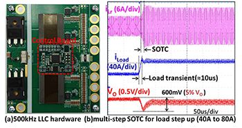
Multi-step SOTC for fast load transient response is verified on a 500kHz LLC converter, which is designed based on Matrix Transformer for LLC Resonant Converters. The hardware is shown in Fig. 2(a). The experimental results of multi-step SOTC for load step up from 40A to 80A are shown in Fig. 2(b).
In summary, the proposed multi-step SOTC settles resonant tank within n-step instead of fixed 2-step, where n is selected based on delay of controller. Multi-step SOTC makes it feasible to use a low-cost MCU to control the high frequency LLC converter, while simultaneously achieving nearly the same performance as simplified optimal trajectory control.


