


LIBRARY
Matrix Transformer for LLC Resonant Converters
Year: 2013
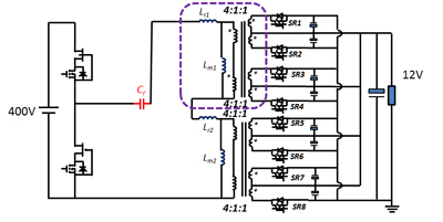
Fig. 1. Proposed LLC Resonant Converter Transformer Structure.
In Fig. 1, the matrix transformer of a LLC resonant converter is built by four small transformers series in primary and parallel in secondary. This transformer helps to reduce leakage induct-ance and winding AC resistance by splitting the secondary side current, while increasing the size and loss of the magnetic cores. To reduce them, two small transformers can merge into one by flu cancellation. However, the winding loss is still high due to the termination loss. Fig. 2 shows one merged transformer winding structure. The SR devices and output capacitors are part of secondary side winding, which can eliminate the AC termination loss and via loss. Based on the FEA simulation results in Fig. 3, the current and magnetic flux distribution are quite even, which means a low AC resistance and leakage inductance. Fig. 4 gives the prototype of the proposed matrix transformer in a 400V/12V, 1kW LLC resonant converter.
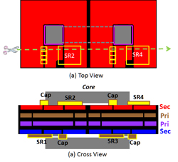
Fig. 2. Proposed Winding Structure.
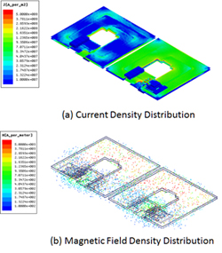
Fig. 3. FEA Simulation results of Proposed Winding Structure.
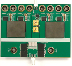
Fig. 4. The prototype of Proposed Matrix Transformer.
