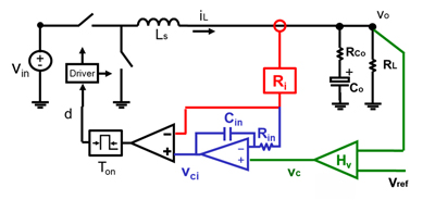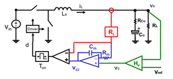
Fig.1 Proposed I2 average current mode control.
The constant frequency average current mode control is a widely used control scheme for the converters requiring precise current control, but its transient response is relatively slow, while the switching loss and driving loss significantly diminish the light load efficiency. To solve these issues, the I
2 control average current mode is proposed. By combining the fast direct current feedback and integral feedback, the I
2 control achieves both high bandwidth and accurate current control. As a particular embodiment of this concept, by adopting constant on-time modulation, constant on-time I
2 control needs no artificial ramp, and has fast dynamic response. Moreover, due to the decrease in the switching frequency, constant on-time I
2 control improves the efficiency in discontinuous-conduction-mode. The concept of I
2 control can be extended to other modulations. A small signal model using a describing function based an equivalent circuit model is proposed. The model is accurate up to 1/2 switching frequency. Based on the model, the design guidelines are discussed.
Fig.1 shows the proposed I
2 average current mode control structure. The current loop consists of a fast direct feedback loop and a slow integral feedback loop. The integration provides a dynamic offset between v
c and v
ci to eliminate a low frequency control error. Voltage loop is the outer loop for voltage regulation. As the current information is used twice in control loop, following the name V
2 control, the proposed control is named as I
2 control.
The I
2 control can achieve fast and accurate current control, without requiring an external ramp. In CCM, as on-time is fixed, the switching frequency f
sw of I
2 control is independent on the inductor value.
When the average current is below half of the inductor current ripple, the circuit operates in discontinuous-conduction-mode (DCM). In DCM, the synchronized rectifier is turned off when the inductor current reverses to minimize efficiency loss due to reverse current flow and gate charge switching.

Fig.2 Transient Response of I2 control in CCM.


