LIBRARY
Power Cycling the IGBT Module and Zth Measurement of Die Attach

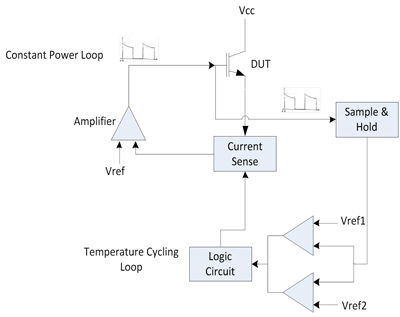
The gate emitter voltage (Vge) of the IGBT is used as a temperature-sensitive parameter to accurately sense the junction temperature (Tj) of the IGBT during transients. A pre-characterized relationship between the junction temperature and the Vge voltage is used to express the junction temperature of the device, directly in terms of corresponding voltage.
Using this temperature - voltage relationship, a window comparator is used to set the two temperature limits in terms of voltages. A high current passed through the IGBT controls the heating of the device. Power dissipated in the IGBT is maintained constant during this time using a feedback loop. The relationship between the junction temperature (Tj) and Vge is measured and utilized at very low current (2 mA) to avoid self-heating. Hence, during the heating phase of the module, the device current is lowered to 2 mA, so that Vge (and thus Tj) is measured for a very short duration (in µs), and then the heating continues. This measured Vge is stored using a sample-and-hold IC until the next measurement.
The Zth of the die attach layer is measured periodically, after a certain number of cycles, using the below equation.

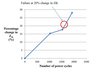
Here, the change in Vge ("Vge) is calculated by measuring Vge before heating and after heating by applying power P. The k-factor denoted by 'k' is obtained from the characterized relationship be-tween Vge and Tj. The criteria for the failure of the die attach joint is a 20% change in the Zth value.
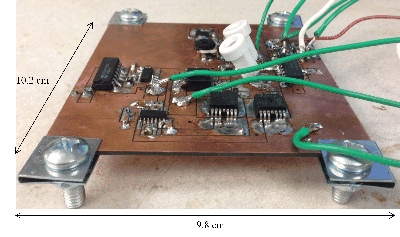
NI USB-6211 hardware and NI LABVIEW software are used to remotely control this entire setup using a PC. The LabVIEW interface on the computer makes controlling and monitoring the setup quite user friendly. The software displays in real time, the number of completed power cycles, time taken for each cycle, measured Zth and other related information, on the computer screen.
The power cycling of the IGBT modules is affected by the temperature limits as well as the frequency of cycling. One of the suggested set of parameters in JEDEC standard JESD-A122 is used. An IGBT module is cycled between 40C and 100C at the frequency of 6 cycles per hour. As seen in the above plot (Fig. 3), it was observed that the sample under test failed at 1700 power cycles.


