LIBRARY
Small-Signal Impedance Measurement in Medium-Voltage DC Power Systems

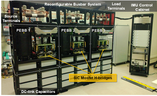
For accurate measurement of both source and load side impedances, the PIU should be able to inject both current in shunt and voltage in series. When in shunt current injection mode, the PIU need to stand full system voltage and inject only a few percent of system current. When in series voltage injection mode, the PIU conducts full system current while injecting only a few percent of the system voltage. A Power Electronics Building Block (PEBB)-based converter is designed for this application. The PEBBs are reconfigured in shunt and series injection modes to serve the two very different ratings, as shown in Fig. 1.
The control block diagram of a shunt current injection mode (in Fig. 2a) and a series voltage injection are given. A fast current loop with a 3 kHz bandwidth is designed to achieve good tracking of the perturation reference signal. The current reference is the sum of the two parts: perturbation reference and output of dc bus voltage control loop, which is designed to have sub-hertz bandwidth so as to not interfere with the perturbation reference. In addition, there is a dc voltage balancing controller designed to deal with the component parameter difference between each PEBB, such as dc capacitance and operation loss. The external loop controls (Fig. 2b) the voltage accros the capacitor, which has two parts. One is the perturbation voltage reference given by the upper level control. The other is the output of dc bus voltage controller.


