LIBRARY
Small-Signal Analysis of the Sigma Converter

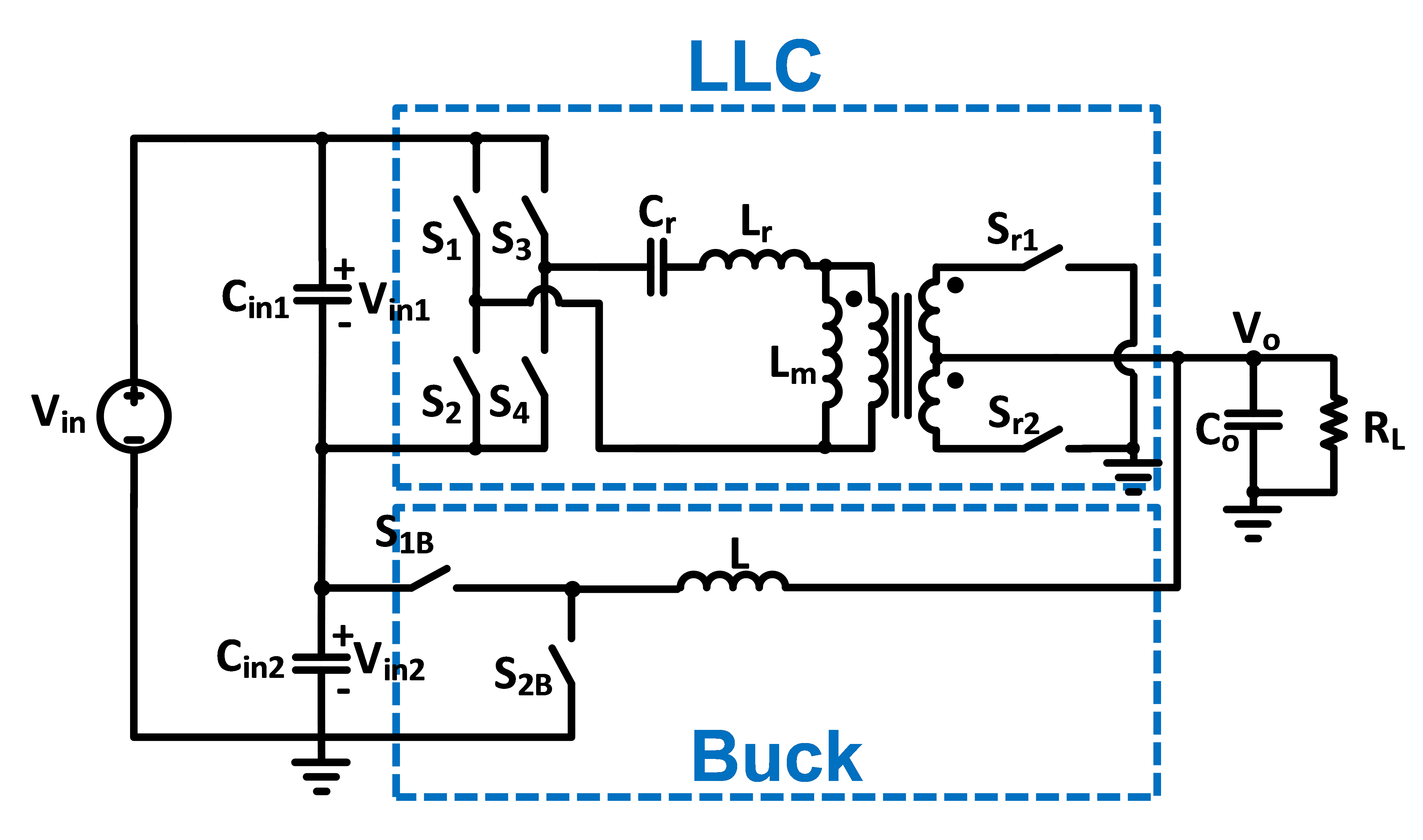
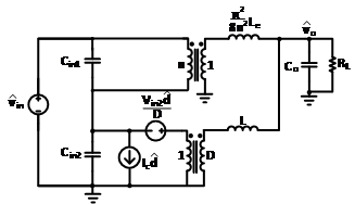
The sigma converter is composed of a fixed-frequency LLC running at the resonant frequency and a buck converter, with the inputs of the converters connected in series and the outputs of the converters connected in parallel, as shown in Fig. 1. The small-signal model of the sigma converter can be obtained by connecting the models of its components in the quasi-parallel con-figuration shown in Fig. 2. For the fixed-frequency LLC running at resonant frequency, a trans-former with turns ratio n:1 and an equivalent inductance is used. For the buck converter, the three-terminal switch model is used.
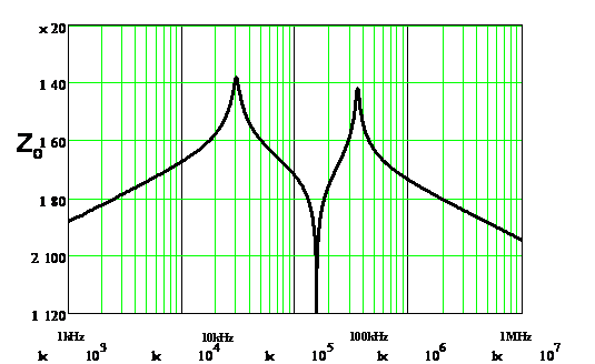
The output of the VR is required by Intel to follow a specific load-line during steady-state for server applications. In order to achieve an accurate load-line, a constant output impedance is needed. Fig. 3 shows the ideal output impedance of a design with parameters of Vin1=40V, Vin2=8V, Vo=1V, fo=fs_LLC=1MHz, fBuck=2MHz, n=40, Cr=110nF, Lr=192nH, Lm=22μH, Cin1=400nF, Cin2=2.1μF, Co=862μF, and RL= 12.5 mΩ. From the Bode plot, two double-poles and a double-zero are observed. To achieve a constant output impedance with the sigma converter, the con-verter components must be carefully designed before control designs are considered.


